G.
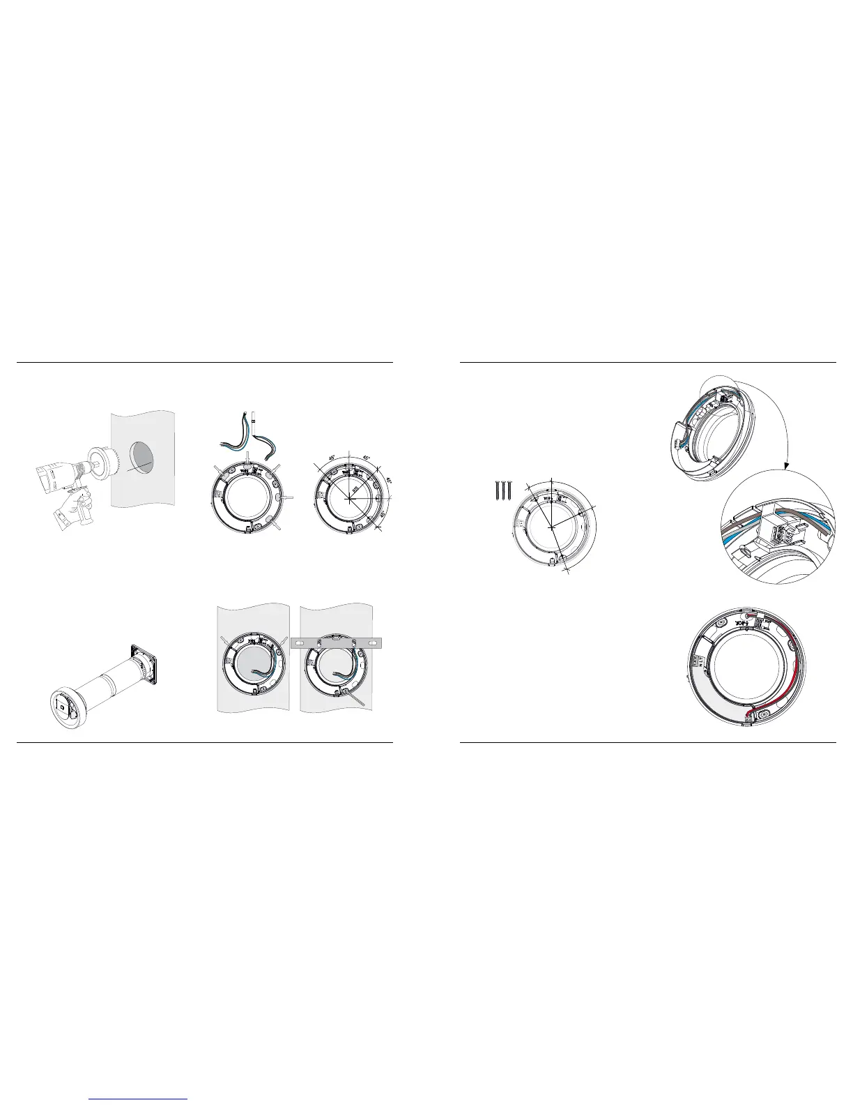
Pax wall pipes and external louvres are available as
accessories (Figure E). The fan’s wall seal has a short
spigot which ts inside the Ø100 mm pipe. Make
sure when mounting to adapt the length of the wall
pipe so it does not push back the wall seal so the
fan impeller cannot rotate. Always customise a wall
pipe, existing or new, so it ends about 5 mm inside
the wall surface where Calima is to be installed. The
wall frame with its seal is prepared with 5 cable entry
H.
I.
R75
30°
65°
95°
J.
points (Figure F) for concealed electrical connec-
tion or surface-mounted cable using the dimension
shown in Figure G.
Make sure that the seal is properly installed on the
wall frame; place it in the appropriate place and
centre it in the wall pipe. The wall frame can be level-
led horizontally by placing a spirit level on its support
points (Figures H and I).
Mark the three attachment points for the appro-
priate screws to the substrate (Figure J).
Pax follows industry regulations for Safe Water in-
stallation, drilling and sealing with silicone according
to the instructions for wooden walls and concrete.
These must be followed. (See page 25).
Tighten the screws so that the seal forms a seal
against the wall
.
All 100-240 V electrical connections must be per-
formed by a qualied electrician. The power must be
cut during all electrical work on the product.
The wall frame contains an electronics component
with terminal blocks for 100-240 V AC and 12 V DC.
Electrical connection can be made according to
the wiring diagram on page 20.
NB: As the two legs of the motor unit protrude
into the wall frame, and one leg is in contact with
the switching contact, cables must be laid in the
wall frame as shown in Figures K/K1 (100-240 V AC
connection) and L (12 V DC connection), so that no
cables block the path of the leg
.
K.
K1.
L.
100-240 V AC
connection
12 V DC connection