22
A1900851
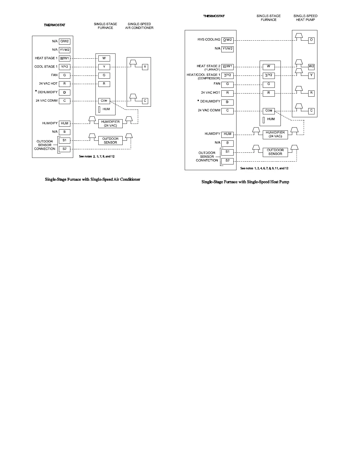
Fig. 26 -- Thermostat Wiring Diagrams
NOTES FOR THERMOSTAT WIRING DIAGRAMS
1. Heat pump MUST have a high pressure switch for HYBRID HEATr dual fuel applications.
2. Refer to outdoor equipment Installation Instructions for additional information and setup procedure.
3. If the heat pump date code is 1501E or earlier, select the “ZONE” position on the two speed heat pump control. Heat pumps with date
code 1601E and later do not have or require a “ZONE” selection.
4. Outdoor Air Temperature Sensor must be attached in all HYBRID HEATr dual fuel applications.
5. Configure the thermostat for air conditioner installations. Refer to thermostat instructions.
6. Configure thermostat for heat pump installations. Refer to thermostat instructions.
7. Configure thermostat for single-stage compressor operation. Refer to thermostat instructions.
8. Configure thermostat for HYBRID HEATr dual fuel operation. Refer to thermostat instructions.
9. NO connection should be made to the furnace HUM terminal when using a thermostat with a 24 volt humidifier output.
10. The RVS Sensing terminal “L” should not be connected. This is used internally to sense defrost operation.
11. If thermostat has internal control of heat pump balance point, DO NOT SELECT the “FURNACE INTERFACE” or “BALANCE
POINT” optio n on the two--speed heat pump control board. Refer to thermostat instructions.
12. Thermostat signals may vary. Consult thermostat installation instructions for more information.