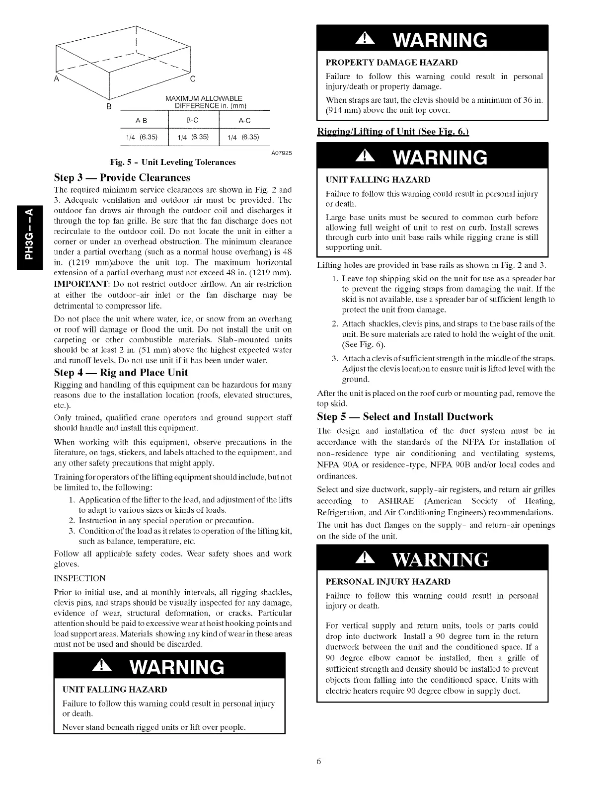
A-B
1/4 (6.35)
MAXIMUM ALLOWABLE
DIFFERENCE in. (mm)
B-C ArC
1/4 (6.35) 1/4 (6.35)
A07925
Fig. 5 - Unit Leveling Tolerances
Step 3 -- Provide Clearances
The required minimum service clearances are shown in Fig. 2 and
3. Adequate ventilation and outdoor air must be provided. The
outdoor fan draws air through the outdoor coil and discharges it
through the top fan grille. Be sure that the fan discharge does not
recirculate to the outdoor coil. Do not locate the unit in either a
corner or under an overhead obstruction. The minimum clearance
under a partial overhang (such as a normal house overhang) is 48
in. (1219 mm)above the unit top. The maximum horizontal
extension of a partial overhang must not exceed 48 in. (1219 mm).
IMPORTANT: Do not restrict outdoor airflow. An air restriction
at either the outdoor-air inlet or the fan discharge may be
detrimental to compressor life.
Do not place the unit where water, ice, or snow from an overhang
or roof will damage or flood the unit. Do not install the unit on
carpeting or other combustible materials. Slab-mounted units
should be at least 2 in. (51 mm) above the highest expected water
and runoff levels. Do not use unit if it has been under water.
Step 4 -- Rig and Place Unit
Rigging and handling of this equipment can be hazardous for many
reasons due to the installation location (root;, elevated structures,
etc.).
Only trained, qualified crane operators and ground support staff
should handle and install this equipment.
When working with this equipment, observe precautions in the
literature, on tags, stickers, and labels attached to the equipment, and
any other safety precautions that might apply.
Training for operators of the lifting equipment should include, but not
be limited to, the following:
1. Application of the lifter to the load, and adjustment of the lifts
to adapt to various sizes or kinds of loads.
2. Instruction in any special operation or precaution.
3. Condition of the load as it relates to operation of the lifting kit,
such as balance, temperature, etc.
Follow all applicable safety codes. Wear safety shoes and work
gloves.
INSPECTION
Prior to initial use, and at monthly intervals, all rigging shackles,
clevis pins, and straps should be visually inspected for any damage,
evidence of wear, structural deformation, or cracks. Particular
attention should be paid to excessive wear at hoist hooking points and
load support areas. Materials showing any kind of wear in these areas
must not be used and should be discarded.
UNIT FALLING HAZARD
Failure to follow this warning could result in personal iniury
or death.
Never stand beneath rigged units or lift over people.
PROPERTY DAMAGE HAZARD
Failure to follow this warning could result in personal
iniury/death or property damage.
When straps are taut, the clevis should be a minimum of 36 in.
(914 mm) above the unit top cover.
Ri_in_/Liftin_ of Unit (See Fire 6.)
UNIT FALLING HAZARD
Failure to follow this warning could result in personal iniury
or death.
Large base units must be secured to common curb before
allowing full weight of unit to rest on curb. Install screws
through curb into unit base rails while rigging crane is still
supporting unit.
Lifting holes are provided in base rails as shown in Fig. 2 and 3.
1. Leave top shipping skid on the unit for use as a spreader bar
to prevent the rigging straps from damaging the unit. If the
skid is not available, use a spreader bar of sufficient length to
protect the unit from damage.
2. Attach shackles, clevis pins, and straps to the base rails of the
unit. Be sure materials are rated to hold the weight of the unit.
(See Fig. 6).
3. Attach a clevis of sufficient strength in the middle of the straps.
Adjust the clevis location to ensure unit is lifted level with the
ground.
After the unit is placed on the roof curb or mounting pad, remove the
top skid.
Step 5 -- Select and Install Ductwork
The design and installation of the duct system must be in
accordance with the standards of the NFPA for installation of
non-residence type air conditioning and ventilating systems,
NFPA 90A or residence-type, NFPA 90B and/or local codes and
ordinances.
Select and size ductwork, supply-air registers, and return air grilles
according to ASHRAE (American Society of Heating,
Refrigeration, and Air Conditioning Engineers) recommendations.
The unit has duct flanges on the supply- and return-air openings
on the side of the unit.
PERSONAL INJURY HAZARD
Failure to follow this warning could result in personal
iniury or death.
For vertical supply and return units, tools or parts could
drop into ductwork Install a 90 degree turn in the return
ductwork between the unit and the conditioned space. If a
90 degree elbow cannot be installed, then a grille of
sufficient strength and density should be installed to prevent
objects from falling into the conditioned space. Units with
electric heaters require 90 degree elbow in supply duct.

 Loading...