Wiring Diagram
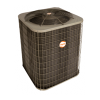
PH14*B
SPLIT--SYSTEM HEAT PUMP
WITH R--410A REFRIGERANT
1--1/2 -- 5 NOMINAL TONS
CAP
H
F
C
339904-101 REV. C
CONDENSING UNIT CHARGING INSTRUCTIONS
For use with units using R-410A refrigerant
COOLING ONLY
CHARGING PROCEDURE
Where a dash (- -) appears do not attempt to charge system under these
conditions or refrigerant slugging may occur. Charge must be weighed in.
Note: Superheat ºF is at low-side service port, allow a tolerance of +/- 3 ºF
Note: Indoor dry bulb between 70 ºF and 80 ºF
* Optimum performance point, 82 ºF outdoor ambient and (80 ºF dry bulb),
(67 ºF wet bulb) indoor conditions. (DOE B Test Conditions)
TABLE I - SUPERHEAT CHARGING TABLE
(SUPERHEAT ºF AT LOW-SIDE SERVICE PORT)
OUTDOOR
TEMP ºF
EVAPORATOR ENTERING AIR º F WB.
67
50 52 54
56 58
60
62
64 68
70
72 74
76
55
60
65
70
75
82
85
90
95
100
105
110
115
11
11 12
12
12
13
17
20 24
24
25
25 25
25
6
6
7
7
712
16 21
22
7
23 23
23 23
3
712
18
19
21
21 22
22
- -
- - - -
- - - -
714
16 18
20
20 20
- -
- - - -
- - - -
- -
- - - -
- - - -
- -
- - - -
- -
3
11
13
16
18
18
19
- -
- - - -
- -- -- -- -
- -
- - - -
- - - - - -
- -
6
8
12
15
16 17
47
11
14
15
16
4
8
12 14 15
610
12 14
4
8
11 1 2
369
11
5
7
10
863
- - - -
- -
- - - -
- - - - - -
- - - -
- -
- - - -
- - - - - -
- - - -
- -
- - - -
- - - - - -
- - - -
- -
- - - -
- - - - - -
- - - -
- -
- - - -
- - - - - -
- - - -
- -
- - - -
- - - - - -
- - - -
- -
- - - -
- -
- - - -
- - - -
- - - -
- - - -
- -
*
TABLE II - REQUIRED SUCTION TUBE TEMPERATURE ºF
(MEASURED AT LOW-SIDE SERVICE PORT)
SUCTION PRESSURE AT SERVICE PORT PSIG.
108
112
117
121 126
131
139
141 146
SUPERHEAT
TEMP. ºF
0
2
4
6
8
10
12
14
16
18
20
22
24
26
28
30
35
37
39 41
43
45
47
49
51
37
39
41 43
45
47
49
51
53
39
41
43 45
47
49
51
53
55
41
43
45 47
49
51
53
55
57
43
45
47 49
51
53
55
57
59
45
47
49 51
53
55
57
59
61
47
49
51 53
55
57
59
61
63
49
51
53 55
57
59
61
63
65
51
53
55 57
59
61
63
65
67
53
55
57 59
61
63
65
67
69
55
57
59 61
63
65
67
69
71
57
59
61 63
65
67
69
71
73
59
61
63 65
67
69
71
73
75
61
63
65 67
69
71
73
75
77
63
65
67 69
71
73
75
77
79
65
67
69 71
73
75
77
79
81
* MAY BE FACTORY OR FIELD INSTALLED
-LEGEND-
CONNECTION DIAGRAM
FIELD SELECTED TIME PERIOD
BETWEEN DEFROST CYCLES (MINUTES)
JUMPERED TEST PINS (USE METAL OBJECT), FIELD SPEED-UP CYCLE
HEAT CYCLE:
90 MIN. ACCELERATED TO 21 SEC.
60 MIN. ACCELERATED TO 14 SEC.
30 MIN. ACCELERATED TO 7 SEC.
10 MIN. ACCELERATED TO 2 SEC.
DEFROST CYCLE:
90
60
30
SPEED
UP
SCHEMATIC DIAGRAM (LADDER FORM)
CAP
*CH
*CHS
COMP
CONT
CB
DFT
DR
*DTS
*HPS
*LLS
*LPS
OFM
RVS
*SC
*SR
*ST
CAPACITOR
CRANKCASE HEATER
CRANKCASE HEATER SWITCH
COMPRESSOR
CONTACTOR
CIRCUIT BOARD
DEFROST THERMOSTAT
DEFROST RELAY & CIRCUITRY
DISCHARGE TEMP. SWITCH
HIGH PRESSURE SWITCH
LIQUID LINE SOLENOID VALVE
LOW PRESSURE SWITCH
OUTDOOR FAN MOTOR
REVERSING VALVE SOLENOID
START CAPACITOR
START RELAY
START THERMISTOR
1. Compressor and fan motor furnished with
inherent thermal protection.
2. To be wired in accordance with National
Electric Code (N.E.C.) and local codes.
3. N.E.C. class 2, 24V circuit, min. 40 VA required,
60 VA on units installed with LLS.
4. Use copper conductors only, from disconnect to unit.
5. Must use thermostat and sub-base as stated
in pre-sale literature.
6. If indoor section has a transformer with a
grounded secondary, connect the grounded
side to "C" on the circuit board.
7. If any of the original wire, as supplied, must
be replaced, use the same or equivalent wire.
8. Check all electrical connections inside control
box for tightness.
9. Do not attempt to operate unit until service
valves have been opened.
10. Use conductors suitable for at least 75ºC (167ºF).
NOTES:
CAUTION
1. Compressor damage may occur if system is
over charged.
2. This unit is factory charged with R-410A in
accordance with the amount shown on the rating
plate. The charge is adequate for most systems
using matched coils and tubing not over 15 feet
long. Check refrigerant charge for maximum
efficiency. See Product Data Literature for
required Indoor air Flow Rates and for use of
line lengths over 15 feet.
3. Relieve pressure and recover all refrigerant
before system repair or final disposal. Use all
service ports and open all flow-control devices,
including solenoid valves.
4. Never vent refrigerant to atmosphere.
Use approved recovery equipment.
1. Operate unit a minimum of 10 minutes
before checking charge.
2. Measure suction pressure by attaching
an accurate gage to suction valve
service port.
3. Measure suction temperature by
attaching an accurate thermistor type
or electronic thermometer to the
suction line at service valve.
4. Measure outdoor air dry-bulb
temperature with a thermometer.
5. Measure indoor air (entering indoor
coil) wet-bulb temperature with a sling
psychrometer.
6. Refer to Table I. Find outdoor
temperature and evaporator entering
air wet-bulb temperature. At this
intersection, note superheat. Where a
dash (- -) appears on table do not
attempt to charge system under these
conditions or refrigerant slugging may
occur. Charge must be weighed in,
adding or removing 0.6 oz/ft of 3/8
liquid line above or below 15 ft.
respectively.
7. Refer to Table II. Find superheat
temperature located in step 6 and
suction pressure. At this intersection
note suction line temperature.
8. If unit has a higher suction line
temperature than charted temperature,
add refrigerant until charted
temperature is reached.
9. If unit has a lower suction line
temperature than charted temperature,
remove and recover refrigerant until
charted temperature is reached.
10. When adding refrigerant, charge in
liquid form into the suction service port
using a flow-restricting device.
11. If outdoor air temperature or pressure
at suction valve changes, charge to
new suction line temperature indicated
on chart.
12. This procedure is valid when indoor air
flow is within +/- 21% of its rated cfm
FACTORY POWER WIRING
FIELD POWER WIRING
FACTORY CONTROL WIRING
FIELD CONTROL WIRING
CONDUCTOR ON CIRCUIT BOARD
COMPONENT CONNECTION
1/4-IN QUICK CONNECT TERMINALS
FIELD SPLICE
JUNCTION
C
RVS
OO
W2
RR
Y
Y
C
DFT
DFT
DR
T1
C
LOGIC
DR
OF1
OF2
L2
L1
COMP
OFM
CAP
*SC
1
2
5
*SR
*S
T
+t°
S
C
R
*H
PS
*LP
S
*D
TS
EQUIP
GND
CONT
* CHS
* CH
11
21
CONT
CONT
23
23
*LPS
*HPS
YEL/PNK
BLU/PNK
*DTS
208/230 1Ø
POWER
SUPPLY
EQUIP GND
L1
L2
BLK
YEL
YEL
OFM
*CH
COMP
BLK
BLK
BLK
*CHS
BLK
or
RED
BLK
RED or BLK
BLK
BLU
BRN
YEL
YEL
S
C
R
*SC
*ST
BRN
BLU
BLU
*SR
+t°
1
2
5
RVS
DFT
PNK
YEL/PNK
BRN
YEL
ORN
ORN
BRN
YEL
CONT
11
21
23
23
GLER
W2
OYC
INDOOR UNIT
TERMINAL BLOCK
ORN
G
W3
LER
W2
OYC
INDOOR
THERMOSTAT
(NOTE #5)
BLK
OF1
OF2
C
O
WHT
W2
RED
R
Y
T1
R
C
C
DFT
O
YEL
Y
PNK
BLU/PNK
90
30
60
W1
SPEED UP
RED
OR
BLUE
RED
OR
BLUE
YEL
H
F
C
Fig. 1 – Wiring Diagram — Model sizes 1-- 1/2 -- 4 tons, 208/230--1