EasyManua.ls Logo

Payne PN1Z036 - User Manual

Payne PN1Z036
28 pages
Print Icon
To Next Page IconTo Next Page
Loading...
Mnstallation
PH1Z024-060
Packaged Heat
Pump Units
Mnstructions
7-03
NOTE: Read the entire instrt/ction manual before starting the installation.
TABLE OF CONTENTS
SAFETY ( ONSIDERATIONS 2
INTRODUCTION 2
RECEIVrNG AND INSTALLATION .......................................................................................................................................................................... 6
Check Equipment ..................................................................................................................................................................................................... 6
IDENTIFY UNIT ................................................................................................. 6
INSPECT SHIPMENT ........................................................................................................................................................................................ 6
Provide Unit Support ................................................................................................................................................................................................ 6
SLAB MOL_T ................................................................................................................................................................................................... 6
GROL ND MOUNT ............................................................................................... 6
Provide ( learances ................................................................................................. 6
Place Unit ................................................................................................................................................................................................................. 6
Select and Install Ductwork ..................................................................................................................................................................................... 6
INSTALL FLANGES FOR DUCTWORK CONNECTIONS (PH1Z060 ONLY) .......................................................................................... 6
CONVERTING HORIZONTAL DISCHARGE UNITS TO DOVv_'FLOW (VERTICAL) DISCHARGE ........................ 7
Provide fbr (ondensate Disposal ..................................................................................... 7
Install Electrical Connections ......................................................................................... 9
HIGH-VOLTAGE CONNECTIONS .................................................................................... 9
ROUTING POWER LEADS INT() UNIT ................................................................................. 9
CONNECTING GROUND LEAD TO E.KIT GROUND ............................................................ l0
ROUTING CONTROL POWER WIRES .............................................................................. 10
ACCESSORY ELECTRIC HEAT WIRING ............................................................................ l0
SPE(IAL PRO(EDURES FOR 208-V OPERATION ................................................................... I 1
PRE-START-L P .................................................................................................... 11
START-UP .............................................................................................................. 12
(heck fbr Refi'igerant Leaks .......................................................................................... 12
LOCATE AND REPAIR REFRIGERANT LEAKS AND (HARGE THE UNIT AS FOLLOWS: ............................. 12
Start=L p Cooling Section and Make Adjustments ........................................................................ 12
CHECKING (OOLING CONTROL OPERATION .................................................................... 12
COMPRESSOR ROTATION ........................................................................................ 13
Refrigerant ( harge .................................................................................................. I3
NO CHARGE .................................................................................................................................................................................................... 13
LOW CHARGE COOLING ............................................................................................................................................................................. 13
T() USE THE COOLING CHARGING CHART ........................................................................................................................................... 13
HEATING MODE CHARGE .......................................................................................................................................................................... 13
Indoor Airflow and Airflow Adjustments ............................................................................................................................................................. 13
FOR 208/230-V ................................................................................................................................................................................................. 14
FOR 460-V MOTORS 14
Lnit Contlols 15
HIGH-PRESSURE RELIEF VALVE .............................................................................................................................................................. 15
LOSS OF CHARGE SWIT(H 15
COMPRESSOR OVERLOAD 15
Sequence of Operation 15
FAN OPERATION 15
(00LING 15
HEAT PUMP HEATING 15
DEFROST 17
ELECTRIC RESISTANCE HEATING 17
Form: tM-PHIZ-02 Cancets: IM-PH1Z-01 Printed in U.S.A. Catalog No. 53PH-1Z7
Question and Answer IconNeed help?

Do you have a question about the Payne PN1Z036 and is the answer not in the manual?

Summary

Safety Considerations

Introduction to PHIZ Units

Receiving and Installation

Procedure 1: Check Equipment

Verify unit model, serial number, and voltage against shipping papers and rating plate for accurate identification.

Procedure 2: Provide Unit Support

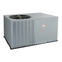
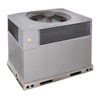
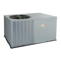
Guidelines for slab and ground mounting, ensuring proper support and level installation of the unit.

Procedure 5: Select and Install Ductwork

Standards for duct system design and installation, including flange attachment for PH1Z060 units.

Procedure 6: Provide for Condensate Disposal

Install Electrical Connections

High-Voltage Connections

Requirements for separate electrical service, disconnect switch, and wire sizing for high-voltage power supply.

Routing Power Leads into Unit

Instructions for running high-voltage leads through conduit and connecting them inside the unit's control box.

Accessory Electric Heat Wiring

Information on installing accessory electric heat, including wiring diagrams and specific instructions.

Special Procedures for 208-V Operation

Transformer Primary Wiring Adjustment

Instructions for rewiring the transformer primary for 208-V operation, ensuring safe power supply.

Pre-Start-Up Procedures

Pre-Start-Up Safety Warnings

Critical warnings for safe pre-start-up operations, including power lockout and handling refrigerant systems.

Unit Start-Up Procedures

Check for Refrigerant Leaks

Locating and repairing refrigerant leaks, reclaiming refrigerant, and charging the unit according to specifications.

Start-Up Cooling Section Adjustments

Procedures for checking cooling control operation, including thermostat settings and reversing valve function.

Compressor Rotation Check

Verifying proper compressor rotation direction to ensure correct operation and prevent damage.

Refrigerant Charge Procedures

Low Charge Cooling

Using cooling charging charts to adjust refrigerant charge based on superheat for optimal cooling performance.

Heating Mode Charge

Guidelines for recovering and weighing in refrigerant for heating mode operations based on unit data.

Indoor Airflow and Airflow Adjustments

Indoor Airflow: 208;230-V Motor Speed

Color-coding of motor leads for changing indoor fan speed on 208/230-V units.

Indoor Airflow: 460-V Motor Speed

Color-coding of motor leads for changing indoor fan speed on 460-V units.

Unit Controls and Safety Devices

Unit Control: High-Pressure Relief Valve

Description of the high-pressure relief valve and its function in protecting the unit from excessive pressure.

Unit Control: Loss of Charge Switch

Function and operation of the low-pressure loss of charge switch for system protection.

Sequence of Operation

Sequence of Operation: Cooling Mode

Operation during cooling mode, including thermostat settings, compressor, and fan engagement.

Sequence of Operation: Heat Pump Heating

Operation during heat pump heating mode, including thermostat control and component engagement.

Defrost Cycle Operation

Defrost Mode Description

Explanation of the defrost cycle, including the timer, thermostat, and use of electric heat.

Electric Resistance Heating Operation

How accessory electric heaters function during 'Emergency Heat' or staged heating operations.

Periodic Maintenance Requirements

Minimum Maintenance Requirements

Monthly air filter inspection and seasonal checks of coils, drain pans, and electrical connections.

Maintenance: Air Filter Inspection

Instructions for inspecting, cleaning, or replacing air filters to ensure proper unit operation and airflow.

Maintenance: Indoor Blower and Motor

Annual cleaning of the indoor blower wheel and motor for optimal performance and continuing efficiency.

Outdoor Fan Maintenance

Outdoor Fan Adjustment

Procedure for adjusting the outdoor fan height and tightening setscrews for proper airflow and operation.

Electrical Controls and Wiring Inspection

Electrical Connection Tightness Check

Annual inspection of electrical controls and wiring for tightness and signs of burning or damage.

Refrigerant Circuit Inspection

Refrigerant Leak Detection

Annual inspection for oil accumulation indicating leaks, and methods for leak testing refrigerant tubing.

Refrigerant Charge Verification

Referencing refrigerant charge amounts and checking system performance against specifications.

Liquid Line Strainer Function

Purpose and location of the liquid line strainer that protects the metering device from debris.

Payne PN1Z036 Specifications

General IconGeneral
RefrigerantR-410A
Phase1
Voltage208/230 V
Cooling Capacity36000 BTU/h
Heating Capacity36000 BTU/h

Related product manuals