Mnstallation
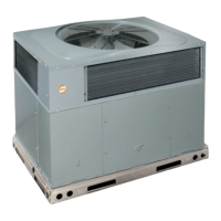
PH1Z024-060
Packaged Heat
Pump Units
Mnstructions
7-03
NOTE: Read the entire instrt/ction manual before starting the installation.
TABLE OF CONTENTS
SAFETY ( ONSIDERATIONS 2
INTRODUCTION 2
RECEIVrNG AND INSTALLATION .......................................................................................................................................................................... 6
Check Equipment ..................................................................................................................................................................................................... 6
IDENTIFY UNIT ................................................................................................. 6
INSPECT SHIPMENT ........................................................................................................................................................................................ 6
Provide Unit Support ................................................................................................................................................................................................ 6
SLAB MOL_T ................................................................................................................................................................................................... 6
GROL ND MOUNT ............................................................................................... 6
Provide ( learances ................................................................................................. 6
Place Unit ................................................................................................................................................................................................................. 6
Select and Install Ductwork ..................................................................................................................................................................................... 6
INSTALL FLANGES FOR DUCTWORK CONNECTIONS (PH1Z060 ONLY) .......................................................................................... 6
CONVERTING HORIZONTAL DISCHARGE UNITS TO DOVv_'FLOW (VERTICAL) DISCHARGE ........................ 7
Provide fbr (ondensate Disposal ..................................................................................... 7
Install Electrical Connections ......................................................................................... 9
HIGH-VOLTAGE CONNECTIONS .................................................................................... 9
ROUTING POWER LEADS INT() UNIT ................................................................................. 9
CONNECTING GROUND LEAD TO E.KIT GROUND ............................................................ l0
ROUTING CONTROL POWER WIRES .............................................................................. 10
ACCESSORY ELECTRIC HEAT WIRING ............................................................................ l0
SPE(IAL PRO(EDURES FOR 208-V OPERATION ................................................................... I 1
PRE-START-L P .................................................................................................... 11
START-UP .............................................................................................................. 12
(heck fbr Refi'igerant Leaks .......................................................................................... 12
LOCATE AND REPAIR REFRIGERANT LEAKS AND (HARGE THE UNIT AS FOLLOWS: ............................. 12
Start=L p Cooling Section and Make Adjustments ........................................................................ 12
CHECKING (OOLING CONTROL OPERATION .................................................................... 12
COMPRESSOR ROTATION ........................................................................................ 13
Refrigerant ( harge .................................................................................................. I3
NO CHARGE .................................................................................................................................................................................................... 13
LOW CHARGE COOLING ............................................................................................................................................................................. 13
T() USE THE COOLING CHARGING CHART ........................................................................................................................................... 13
HEATING MODE CHARGE .......................................................................................................................................................................... 13
Indoor Airflow and Airflow Adjustments ............................................................................................................................................................. 13
FOR 208/230-V ................................................................................................................................................................................................. 14
FOR 460-V MOTORS 14
Lnit Contlols 15
HIGH-PRESSURE RELIEF VALVE .............................................................................................................................................................. 15
LOSS OF CHARGE SWIT(H 15
COMPRESSOR OVERLOAD 15
Sequence of Operation 15
FAN OPERATION 15
(00LING 15
HEAT PUMP HEATING 15
DEFROST 17
ELECTRIC RESISTANCE HEATING 17
Form: tM-PHIZ-02 Cancets: IM-PH1Z-01 Printed in U.S.A. Catalog No. 53PH-1Z7