4 Install2 hando%m_ed flanges onto return air opening in holes provided to %m_ a rectangle aronnd the remm air opening
5 Install remaining 2 handoformed flanges around discharge air opening in holes provided
6. Ductwork can now be attached to flanges.
When designing and installing ductwork, consider the following:
L,_ CAUTION: When connecting ductwork to units, do not drii[ deeper than 3/4 inch in shaded area shown in Fig. 7 or coi[
may be damaged.
* All units should have field-supplied filters installed in the returnoair side of the unit. Recommended sizes %r filters are shown in Table 1.
Avoid abrupt duct size increases and reductions. Abrupt change in duct size adversely affects air per_bm_ance.
mMPORTANT: Use flexible connectors between dnctwork and unit to prevent transmission of vibration. Use suitable gaskets to ensure
weathertight and airtight seal. When electric heat is installed, use fire proof canvas (or similar heat resistant material) connector between ductwork
and unit discharge connection. If flexible duct is used, insert a sheet metal sleeve inside duct. Heat resistant duct connector (or sheet metal sleeve)
must ectend 24 in. fi'om d_e unit discharge connection flange into the dt/ctwork.
* Size ductwork tbr cooling air quantity (cfm). The mininmm air quanti w for proper electric heater operation is listed in Table 2. Heater limit
switches may trip at air quantities below those recommended.
* Insulate and weatherproof all external dnctwork. Insulate and cover with a vapor barrier all ductwork passing through conditioned spaces.
Follow latest Sheet Metal and Air Conditioning Contractors National Association (SMACNA) and Air Conditioning Contractors Association
(A(CA) minin-mm installation standards for residential heating and air conditioning systems.
* Secure all dt_cts to building structure. Flash, weatherproofS, and vibration-isolate duct openings in wall or roof according to good construction
practices.
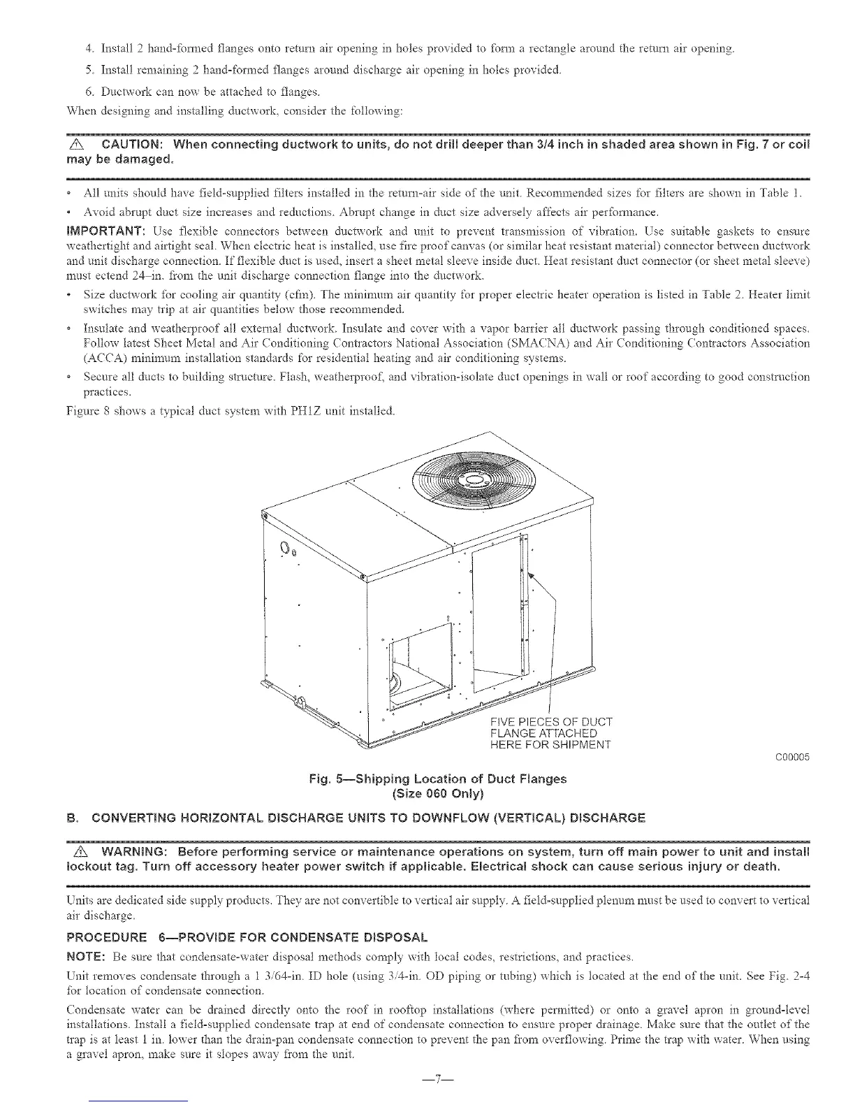
Figure 8 shows a typical duct system with PH1Z unit installed.
FIVE PIECES OF DUCT
FLANGE ATTACHED
HERE FOR SHIPMENT
Fig. 5--Shipping Location of Duct Ftanges
(Size 060 Only)
C00005
B. CONVERTING HORIZONTAL DISCHARGE UNITS TO BOWNFLOW {VERTICAL) DISCHARGE
A WARNBNG: Before performing service or maintenance operations on system, turn off main power to unit and install
lockout tag. Turn off accessory heater power switch if applicabme. Emectrical shock can cause serious injury or death.
Lnits are dedicated side supply products. They are not convertible to vertical air supply A fieldosupplied plenum must be used to convert to vertical
air discharge.
PROCEDURE g--PROVIDE FOR CONDENSATE DISPOSAL
NOTE: Be sure that condensate-water disposal methods comply with local codes, restrictions, and practices.
Unit removes condensate through a 1 3id4oin. ID hole (using 3/4oin. OD piping or tubing) which is located at the end of the unit. See Fig. 2=4
for location of condensate connection.
Condensate water can be drained directly onto the roof in rooftop installations (where pei_aitted) or onto a gravel apron in groundotevel
installations. Install a fieldosupplied condensate tlap at end of condensate connection to ensure proper &ainage. Make sure that the outlet of the
trap is at least 1 in. lower dtan the &ain-pan condensate connection to prevent the pan fi'orn overflowing. Prime the trap with water. When using
a gravel apron, make sure it slopes away fi'om the unit.
7