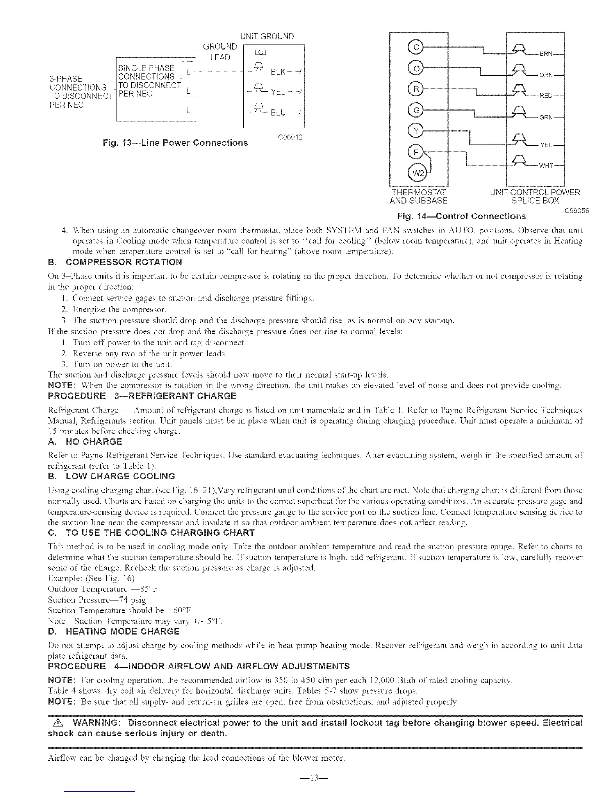
GROUND
[S'NGLE-PHASE []-_ LEAD
3-PHASE |CONNECTIONS q
CONNECTIONS ITO DISCONNECT1 .
TO DtSCONNECT1PER NEC L_-
PER NEC | L
h
UNIT GROUND
- -L]_]
Fig, 13--Line Power Connections
C00012
B.
©
@
@
©
LJJ_
L_
L_
LJ_
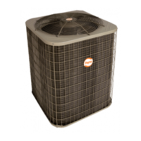
Fig, 14--Control Connections
4 When using art automatic changeover room thermostat, place both SYSTEM and FAN switches in AUTO positions. Observe that unit
operates in Cooling mode when temperatore control is set to "call for cooling" (below room temperature), and unit operates in Heating
mode when temperature control is set to "call for heating" (above room temperature).
COMPRESSOR ROTATION
--[--
THERMOSTAT UNIT CONTROL POWER
AND SUBBASE SPLICE BOX
C99056
On 3 Phase units it is important to be certain compressor is rotating in the proper direction. To determine whether or not compressor is rotating
in the proper direction:
1. Connect service gages to suction and discharge pressure fittings.
2. Energize the compressor.
3. The suction pressure should drop and the discharge pressure should rise, as is normal on any start-up.
[f the suction pressure does not &op and the discharge pressure does not rise to normal levels:
1. Turn off power to the unit and tag disconnect.
2. Reverse any [wo of the unit power leads.
3. Turn on power to the unit.
The suction and discharge pressure levels should now move to their normal start-up levels.
NOTE: When the compressor is rotation in the wrong direction, the unit makes an elevated level of noise and does not provide cooling.
PROCEDURE 3--REFRIGERANT CHARGE
Refrigerant (harge Amount of refrigerant charge is listed on unit nameplate and in Table I. Re_I [o Payne Ret'rigerant Service Techniques
Manual, Refrigerants section. Unit panels must be in place when unit is operating during charging procedure. Unit must operate a minin_um of
15 minutes befbre checking charge.
A. NO CHARGE
RefeI to Payne Ret'rigerant Service Techniqnes Use standard evacuating techniques. At'ter evacuating system_ weigh in the specified amount of"
refi'igerant (refer to Table 1).
B. LOW CHARGE COOLmNG
[sing cooling charging chart (see Fig. 16 2 I)_Vary rei?igerant until conditions of the chart are met. Note that charging chart is different fiom those
normally used (harts are based on charging the units to the con'ect superheat [br the various operating conditions An accurate pressure gage and
temperature-sensing device is required Connec_ the pressure gauge to the service port on the suction line Connect temperature sensing device to
the suction line near the compressor and insulate it so 4]at outdoor ambient temperature does not affkct reading.
C. TO USE THE COOLING CHARGING CHART
This method is to be used in cooling mode only. Take the outdoor ambient temperature and read the suction pressure gauge. Refer to charts to
determine what the suction temperature should be. If suction temperature is high, add refrigerant. If suction temperatore is low, carefully recover
some of the charge. Recheck the suction pressure as charge is adjusted.
Example: (See Fig. 16)
Outdoor Temperature 85°F
Suction Pressure74 psig
Suction Temperature should b_60_T
Note Suction Temperature may vary +/- 5°F
D. HEATING NODE CHARGE
Do not attempt to adjust charge by cooling methods while in heat pump heating mode Recover refi'igerant and weigh in according to unit data
plate refi'igerant data.
PROCEDURE 4--mNDOOR AIRFLOW AND A_RFLOW ADJUSTMENTS
NOTE: For cooling operation, the recommended airflow is 350 to 450 cfm per each 12,000 Btuh of rated cooling capacity.
Table 4 shows dW coil air delive W for horizontal discharge traits. Tables 5-7 show pressure drops_
NOTE: Be sure that all supply= and return-air grilles are open, fi'ee fiom obstructions, and adjusted properly.
Z_ WARNING: Disconnect electrical power to the unit and install lockout tag before changing Mower speed. Electrical
shock can cause serious injury or death.
Airflow can be changed by changing the lead connections of the blower motor.
13