C _ - .BRN....(C,OM_AON_)
wl_.,_ - _vLo_sT_p_2L_
UNIT POWER
WIRING
FUSE BLOCK
L2_ YEL
m
|
|
l CONTACTOR 2
I l
CONTACTOR 1
EL_ AUTO-LIMIT BLK
co06RT i
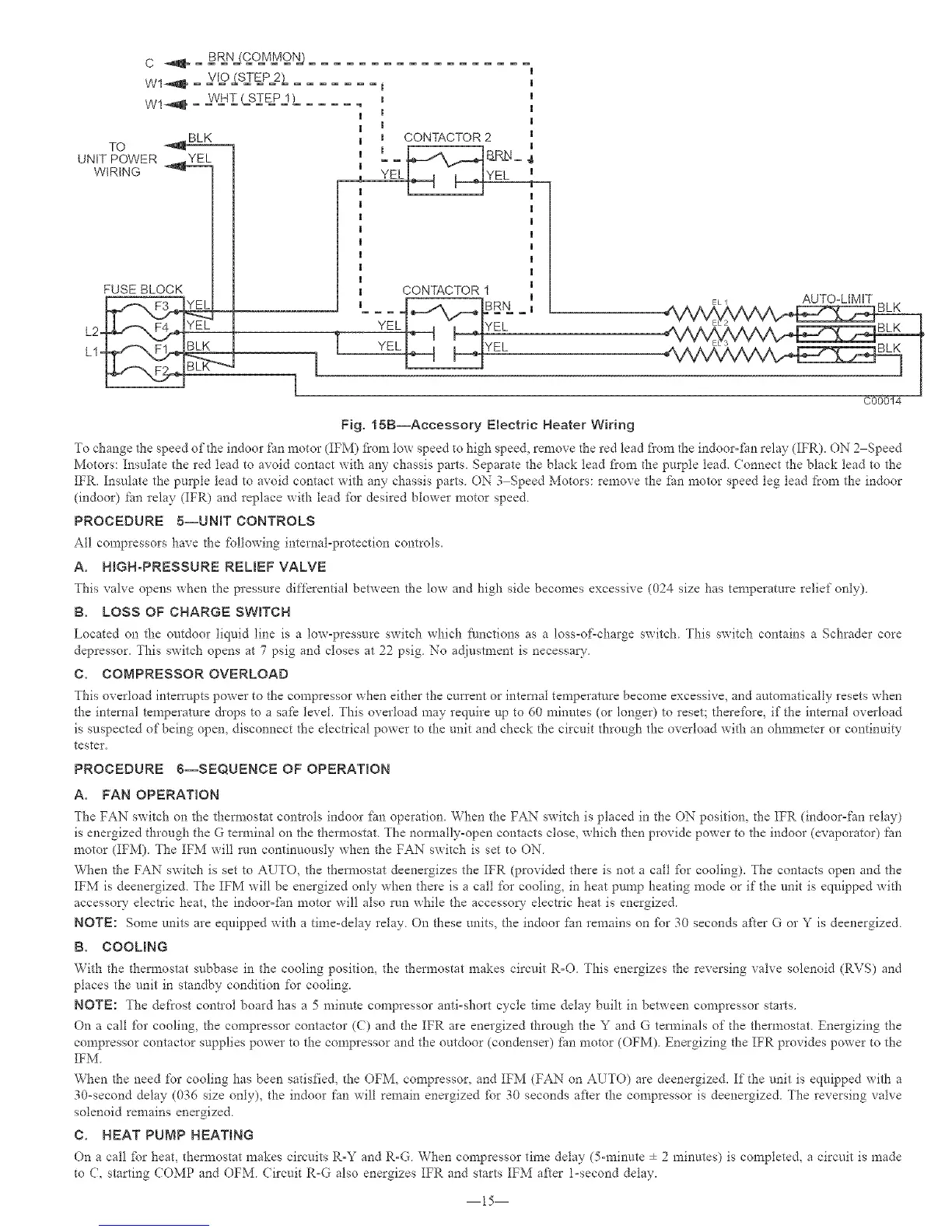
Fig. 15B--Accessory Electric Heater Wiring
To change the speed of the indoor fan motor (IFM) f?om tow speed to high speed, remove the red lead flora the indoor-fhn relay (IFR). ON 2 Speed
Motors: Insulate the red lead to avoid contact with any chassis parts. Separate the black lead fl'om the purple lea& Connect the black lead to the
IFR. Insulate the pmple lead to avoid contact with any chassis parts ON 3 Speed Motors: remove the fhn motor speed leg lead ['tom the indoor
(indoor) tim relay (IFR) and replace with lead fbr desired blower motor speed
PROCEDURE 5--UNBT CONTROLS
All compressors have the fbllowing internal-protection controls.
A. HGH-PRESSURE RELIEF VALVE
This valve opens when the pressure differential between the low and high side becomes excessive (024 size has temperature relief only)
B. LOSS OF CHARGE SWITCH
Located on the outdoor liquid line is a low-pressure switch which functions as a loss-of-charge switch This switch contains a Schrader core
depressor, This switch opens at 7 psig and closes at 22 psig No adiustment is necessa W
C. COMPRESSOR OVERLOAD
This overload interrupts power to the compressor when either the cmrent or internal temperature become excessive, and automatically resets when
the internal temperature &ops to a safe level. This overload may require up to 60 minutes (or longer) to reset; therefbre, if the internal overload
is suspected of being open, disconnect the elecnical power to the unit and check the circuit through the overload with an ohmmeter or continuity
tester.
PROCEDURE 6--SEQUENCE OF OPERATION
A. FAN OPERATION
_he FAN switch on the thermostat controls indoor fhn operation. When the FAN switch is placed in the ON position, the IFR (indoor-fan relay)
is energized through the G terminal on the thermostat The normally-open contacts close, which then provide power to the indoor (evaporator) _m
motor (IFM) The IFM will run continuously when the FAN switch is set to ON
When the FAN switch is set to AUTO, the thermostat deenergizes the IFR (provided there is not a call fbr cooling). The contacts open and the
IFM is deenergized The IFM will be energized only when there is a call for cooling, in heat pmnp heating mode or if the unit is equipped with
accesso_ electric heat, the indoor=tim motor will also run while the accessory electric heat is energize&
NOTE: Some units are equipped with a time-delay relay On these units, the indoor ihn remains on i\_r 30 seconds after G or Y is deenergized
B. COOLING
With the thermostat snbbase in the cooling position, the thermostat makes circuit R-O This energizes the reversing vah-e solenoid (RVS) and
places the unit in standby condition for cooling.
NOTE: The defrost control board has a 5 minute compressor anti-short cycle time delay built in between compressor starts.
On a call for cooling, the compressor contactor (C) and d_e IFR are energized through the Y and G terminals of the thermostat Energizing the
compressor contactor supplies power to the compressor and the outdoor (condenser) tim motor (OFM) Energizing the IFR provides power to the
IFM.
When the need for cooling has been satisfied, the OFM, compressor, and IFM (FAX' on AUTO) are deenergized. If the unit is equipped with a
30-second delay (036 size only), the indoor fan will remain energized ibr 30 seconds after the compressor is deenergized The reversing valve
solenoid remains energized
C. HEAT PUMP HEATING
On a call fbr heat, thermostat makes circuits R-Y and R-G. Vv'hen compressor time delay (5-minute ÷ 2 minutes) is completed, a circuit is made
to C, starting COMP and OFM. (ircuit R-G also energizes IFR and starts IFM after 1-second delay.
15
 Loading...