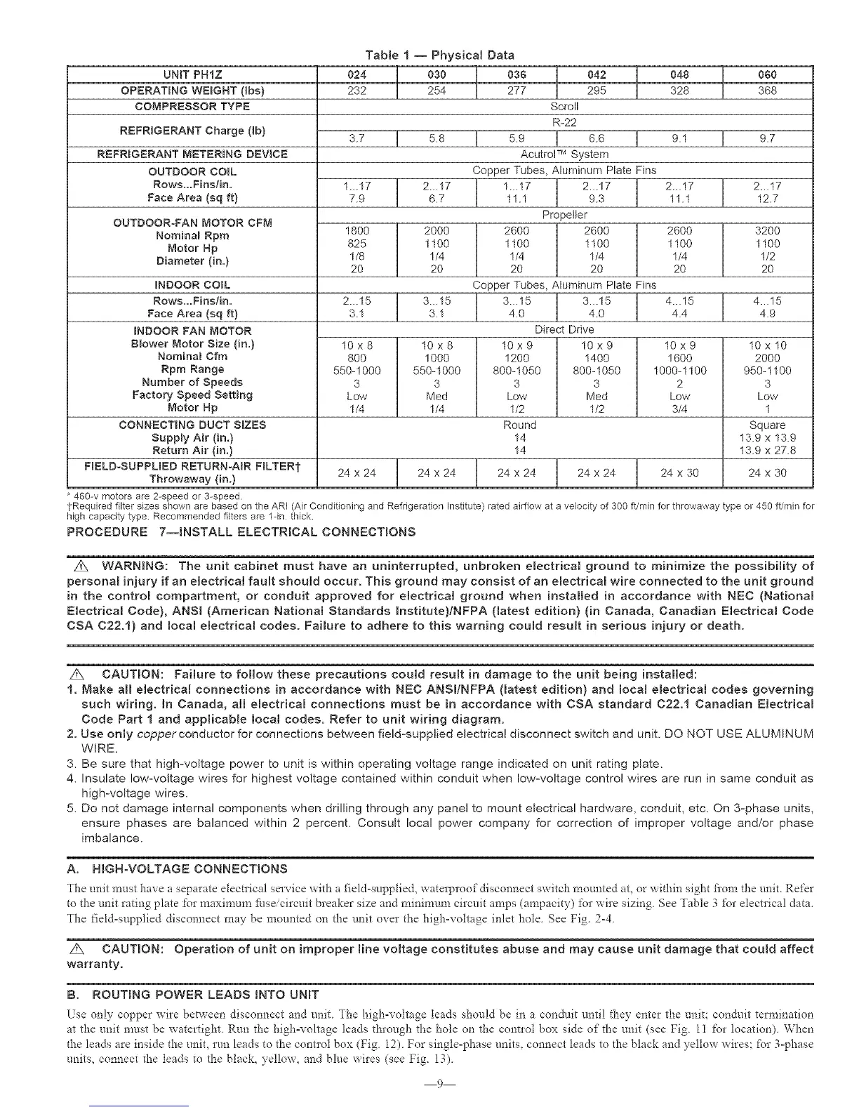
Table I -- Physical Data
UNiT PHIZ 024 030 036 048 060
OPERATING WEBGNT (_bs) 232 254 277 328 368
COMPRESSOR TYPE
REFRIGERANT Charge (tb)
REFRBGERANT METERBNG DEVICE
OUTDOOR COIL
Rows...Fins/in.
Face Area (sq ft)
OUTDOOR-FAN MOTOR CFM
Nomina_ Rpm
Motor Np
Diameter (in.)
INDOOR COBL
Rows...Fins/in.
Face Area (sq ft)
INDOOR FAN MOTOR
B_ower Motor Size (in.)
Nominal Cfm
Rpm Range
Number of Speeds
Factory Speed Setting
Motor Np
CONNECTING DUCT SBZES
SupNy Air (in.)
Return Air (in.)
FIELD-SUPPLBED RETURN-AIR FILTERt
Throwaway (in.)
460-v motors are 2-speed or 3-speed
042
295
Scroll
R-22
3.7 I 5.8 I 5.9 I 6.6 I 9.1 I 9.7
AcutroF M System
Copper Tubes, Aluminum Plate Fins
1...17 2...17 2...17 2...17
7.9 6.7 11.1 12.7
1800 2000
825 1100
1/8 1/4
20 20
1._17 2...17
11.1 9.3
Pro _etter
2600 2600
1100 1100
1/4 1/4
20 20
26OO
1100
1/4
2O
32OO
1100
1/2
2O
2._15 3...15 4...15 4...15
3.1 3.1 4.4 4.9
Copper Tubes, Aluminum Plate Fins
3._15 3._15
4.0 4.0
Direct Drive
10x9
1200
800-1050
3
Low
1/2
Round
14
14
10 x 9
1400
800-1050
3
Med
1/2
10x8
1000
550-1000
3
Med
1/4
10x9
1600
1000-1100
2
Low
3/4
10x8
8OO
550-1000
3
Low
1/4
10 x 10
2000
950-1100
3
Low
1
Square
13.9 x 13.9
13.9 x 27.8
24 x 24 24 x 24 24 x 24 24 x 24 24 x 30 24 x 30
fRequired filter sizes shown are based on the ARI (Air Conditioning and Refrigeration Institute) ratedairflow at avelocity of 300 ft/min for throwaway type or 450 ft/min for
high capacity type Recommended filters are 1-in thick.
PROCEDURE 7--BNSTALL ELECTRICAL CONNECTIONS
Z_ WARNING: The unit cabinet must have an uninterrupted, unbroken electrical ground to minimize the possibility of
persona[ injury if an electrical fault should occur. This ground may consist of an electrical wire connected to the unit ground
in the control compartment, or conduit approved for electrical ground when installed in accordance with NEC (Nationam
Electrical Code), ANSI (American National Standards mnstitute)/NFPA (latest edition) (in Canada, Canadian Electrical Code
CSA C22.1) and local electrical codes. Failure to adhere to this warning could result in serious injury or death.
z_ CAUTION: Failure to follow these precautions could result in damage to the unit being installed:
1. Make aH electrical connections in accordance with NEC ANSl!NFPA (matest edition) and Bocat electricam codes governing
such wiring. Bn Canada, aH electricam connections must be in accordance with CSA standard 022.1 Canadian Electrical
Code Part 1 and applicable Bocal codes. Refer to unit wiring diagram.
2. Use only copper conductor for connections between field-supplied electrica! disconnect switch and unit. DO NOT USE ALUMINUM
WIRE.
3. Be sure that high-voltage power to unit is within operating voltage range indicated on unit rating plate.
4. Insulate low-voltage wires for highest voltage contained within conduit when low-voltage control wires are run in same conduit as
high-voltage wires.
5. Do not damage internal components when drilling through any panel to mount electrical hardware, conduit, etc. On 3-phase units,
ensure phases are balanced within 2 percent. Consult local power company for correction of improper voltage and/or phase
imbalance.
A, HGHoVOLTAGE CONNECTIONS
The unit must have a separate electlical service with a field-supplied, waterproof disconnect switch mounted at, or within sight fiom the uniL Refer
to the unit rating plate for maximum/i_seicircuit breaker size and minimum circuit amps (ampacity) for wire sizing. See Table 3 for electrical data.
The field-supplied disconnect may be mounted on the unit over the high-voltage inlet hole. See Fig. 2-4.
Z_ CAUTION: Operation of unit on improper line voltage constitutes abuse and may cause unit damage that could affect
warranty.
B. ROUTING POWER LEADS BNTO UNBT
Lse only copper wire between disconnect and enit The high-voltage leads shouM be in a conduit until they enter the unit; conduit te_]aination
at the unit must be watertight. Run the highovoltage leads through the hole on the contlol box side of the unit (see Fig. 11 for location). When
the leads are inside _he unit, run leads to the conhol box (Fig. 12). For single-phase units, connect leads to the black and yellow wires; for 3-phase
units, connect the leads to the black, yellow, and blue wires (see Fig. 13).
g