F. SPECIAL PROCEDURES FOR 208oV OPERATION
A WARNING: Make sure that the power suppmy to the unit is switched OFF and instal1 lockout tag before making any
wiring changes. Electrical shock can cause serious injury or death.
1. Remove wirenut from connection of ORG wire to BLK wire Disconnect the ORG transl\_rmer-primary lead fi'om the BLK wire. Save
wirenut See unit wiring label.
2 Remove the wirenut fi'om the terminal on the end of the RED transfom_er-prinlary lead.
3 Save the wirenut.
4 Connect the RED lead to the BLK wire fi'om which the ORG lead was disconnected. Insulate with wirenut flora Step 1.
5 Ersing the wirenut removed fi'om d_e RED lead, insulate the loose tem_inal on the ORG lead
6 Wrap the wirenuts with electrical tape so that the metal terminals cannot be seen
Indoor blower-motor speeds may need to be changed for 208-v operation. RefBr to Indoor Airflow and Airflow A({iustments section. (See Table
of (ontents for page number.)
PRE°START-UP
Z_ WARNING: Failure to observe the following warnings could result in serious injury or death:
1. Follow recognized safety practices and wear protective goggles when checking or servicing refrigerant system.
2. Do not operate compressor or provide any electric power to unit unless compressor terminal cover is in place and secured.
3. Do not remove compressor terminal cover until aH electrical sources are disconnected and lockout tag is installed.
4. Relieve a[[ pressure from both high- and Bow-pressure sides of the system before touching or disturbing anything inside
terminal box if refrigerant leak is suspected around compressor terminals. Use accepted methods to recover refrigerant.
5. Never attempt to repair soldered connection white refrigerant system is under pressure.
6. Do not use torch to remove any component. System contains oH and refrigerant under pressure. To remove a component,
wear protective goggles and proceed as follows:
a. Shut off electrical power to unit and install lockout tag.
b. Relieve aH refrigerant from system using both high- and low-pressure ports. Use accepted methods to recover
refrigerant.
c. Cut component connecting tubing with tubing cutter and remove component from unit.
d. Carefully unsweat remaining tubing stubs when necessary. Oil can ignite when exposed to torch flame.
[se the Start:Up Checklist supplied at the end of this book and proceed as follows to inspect and prepare the unit for initial start:up:
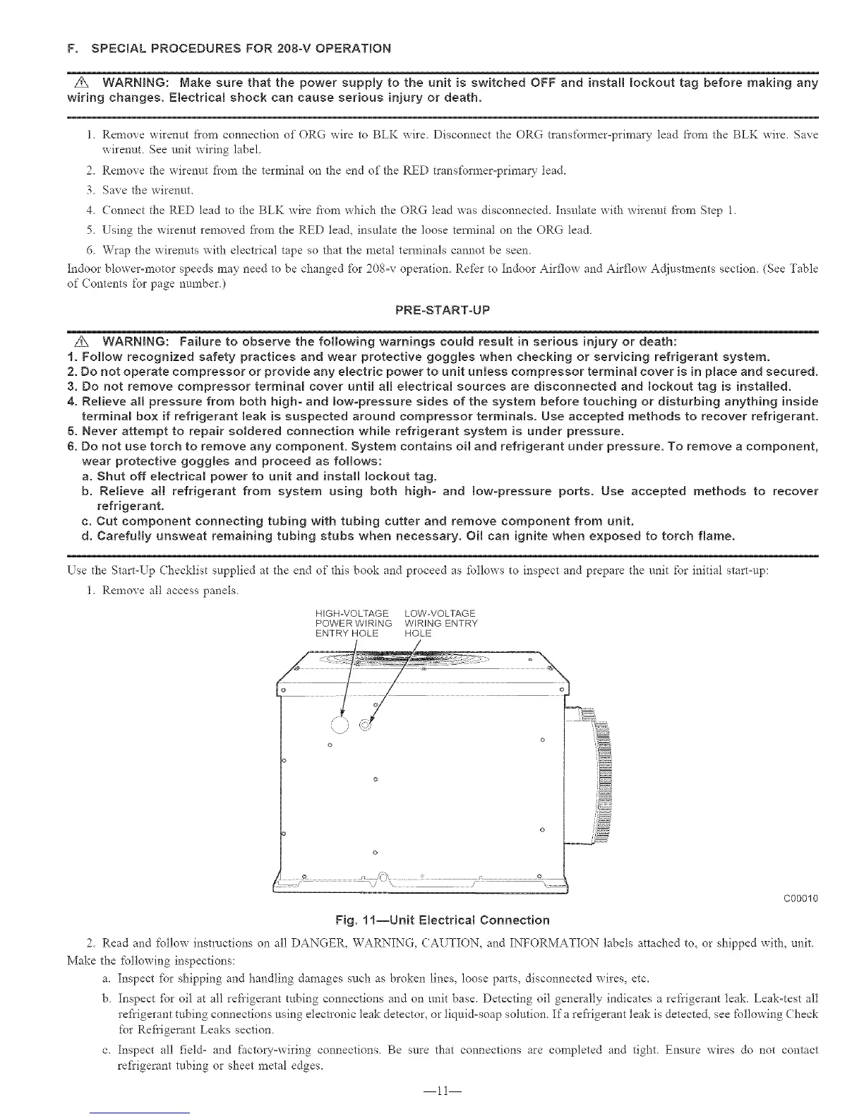
1. Remove all access panels.
HIGH-VOLTAGE LOW-VOLTAGE
POWER WIRING WIRING ENTRY
ENTRY HOLE HOLE
;i;./ ..............................,.' IZIIIII%....................\--
C00010
Fig. ll--Unit Electrical Connection
2. Read and follow instructions on all DANGER, WARNING, CAUTION, and INFORMATION labels attached to, or shipped with, unit.
Make the following inspections:
a. Inspect fbr shipping and handling damages such as broken lines, loose parts, disconnected wires, etc.
b. Inspect _br oil at all reti'igerant tubing connections and on unit base. Detecting oil generally indicates a refrigerant leak. Leak-test all
rei'rigerant tubing connections using electronic leak detector, or liquid-soap solution. If a refi'igerant leak is detected, see following Check
for Refi'igerant Leaks section.
c. Inspect all t_eld- and factory-wiring connections. Be sure that connections are completed and tight. Ensure wires do not contact
refi'igerant robing or sheet metal edges.
11
 Loading...