Installation Instructions
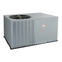
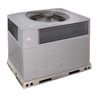
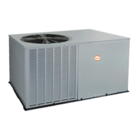
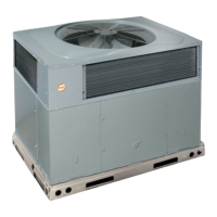
PH3A, PH4A
R--410A SPLIT--SYSTEM
HEAT PUMP
1--1/2 -- 5 T ONS (018--060)
SAFETY CONSIDERATIONS
Improper installation, adjustment, alteration, service, maintenance,
or use can cause explosion, fire, electrical shock, or other
conditions which may cause death, personal injury, or property
damage. Consult a qualified installer, service agency, or your
distributor or branch for information or assistance. The qualified
installer or agency must use factory--authorized kits or accessories
when modifying this product. Refer to the individual instructions
packaged with the kits or accessories when installing.
Follow all safety codes. Wear safety glasses, protective clothing,
and work gloves. Use quenching cloth for brazing operations.
Have fire extinguisher available. Read these instructions
thoroughly and follow all warnings or cautions included in
literature and attached to the unit. Consult local building codes and
National Electrical Code (NEC) for special requirements.
Recognize safety information. This is the safety--alert symbol
!
!
When you see this symbol on the unit and in instructions or
manuals, be alert to the potential for personal injury. Understand
these signal words: DANGER, WARNING, and CAUTION. These
words are used with the safety-- alert symbol. DANGER identifies
the most serious hazards which will result in severe personal injury
or death. WARNING signifies hazards which could result in
personal injury or death. CAUTION is used to identify unsafe
practices which may result in minor personal injury or product and
property damage. NOTE is used to highlight suggestions which
will result in enhanced installation, reliability, or operation.
!
WARNING
ELECTRICAL SHOCK HAZARD
Failure to follow this warning could result in personal
injury or death.
Before installing, modifying, or servicing system, main
electrical disconnect switch must be in the OFF position.
There may be more than 1 disconnect switch. Lock out
and tag switch with a suitable warning label.
!
WARNING
UNIT OPERATION AND SAFETY HAZARD
Failure to follow this warning could result in personal injury
or equipment damage.
R-- 410A refrigerant systems operate at higher pressures than
standard R -- 22 systems. Do not use R-- 22 service equipment
or components on R-- 410A refrigerant equipment.
GENERAL
INSPECT NEW UNIT
After uncrating unit, inspect thoroughly for hidden damage. If
damage is found, notify the transportation company immediately
and file a concealed damage claim.
LOCATION
Check local codes for regulations concerning zoning, noise,
platforms, and other issues.
Locate unit away from fresh air intakes, vents, or bedroom
windows. Noise may carry into the openings and disturb people
inside.
Locate unit in a well drained area, or support unit high enough so
that water runoff will not enter the unit.
Locate unit away from areas where heat, lint, or exhaust fumes will
be discharged onto unit (as from dryer vents).
Locate unit away from recessed or confined areas where
recirculation of discharge air may occur (refer to CLEARANCES
section of this document).
Roof--top installation is acceptable providing the roof will support
the unit and provisions are made for water drainage and
noise/vibration dampening.
NOTE: Roof mounted units exposed to wind may require wind
baffles. Consult the manufacturer for additional information.
CLEARANCES
When installing, allow sufficient space for airflow clearance,
wiring, refrigerant piping, and service. Allow 30 in. (762 mm)
clearance to service end of unit and 48 in. (1219 mm) above unit.
For proper airflow, a 6 in. (152 mm) clearance on 1 side of unit and
12 in. (305 mm) on all remaining sides must be maintained.
Maintain a distance of 24 in. (610 mm) between units or 18 in.
(457 mm) if no overhang within 12 ft. (7.3 m). Position so water,
snow, or ice from roof or eaves cannot fall directly on unit.
On rooftop applications, locate unit at least 6 in. (152 mm) above
roof surface.
Do not install unit under roof overhangs unless gutters are present.
A minimum vertical clearance of 48 inches (1219 mm) is required
to the overhang.
Inside corner locations on single story structures require
evaluation. Large overhanging soffit may cause air recirculation in
a corner area even though recommended minimum clearances are
maintained. As a guide, locate the unit far enough out so that half
of the discharge grille is out from under the soffit.
When placing two or more units side-- by--side, provide a minimum
of 18 inches (457 mm) between units.
Provide minimum service clearance of 24 inches (610 mm) from
control box corner and side service panel.