3
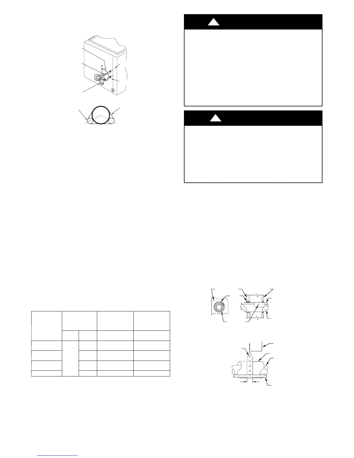
When installing a hard shut--off TXV on an indoor coil, follow the
instructions provided with the new TXV.
A typical hard shut--off TXV installation is shown in Fig. 2.
HARD
SHUT OFF
TXV
SENSING
BULB
EQUALIZER
TUBE
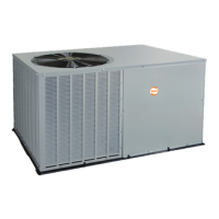
8 O’CLOCK 4 O’CLOCK
STRAP
SENSING BULB
(EITHER SIDE)
SUCTION
TUBE
INDOOR
COIL
SUCTION
TUBE
LIQUID
TUBE
A07587
Fig. 2 --- T ypical TXV Installation
B. REFRIGERANT LINE SETS
The refrigerant line set must be properly sized to assure maximum
efficiency and proper oil circulation. Select line set tube diameters
as specified in Table 1.
NOTE: Total line set length must not exceed 200 feet (61 m).
NOTE: A crankcase heater must be used when the refrigerant line
length exceeds 80 feet (24 m).
If outdoor unit is more than 10 feet (3 m) higher than the indoor
coil, refer to the Extended Length Refrigeration Piping Manual for
instructions.
NOTE: When the outdoor unit is higher than the indoor coil, the
vertical separation must not exceed 100 feet (31 m).
NOTE: When the outdoor unit is lower than the indoor coil, the
vertical separation must not exceed 50 feet (15 m).
If it is necessary to add refrigerant line in the field, use dehydrated
or dry, sealed, deoxidized, copper refrigeration tubing. Do not use
copper water pipe.
Do not remove rubber plugs or caps from copper tubing until
connections are ready to be made.
Be extra careful when bending refrigeration tubing. Tubing can
“kink” easily, and if this occurs, the entire length of tubing must be
replaced.
Table 1—R -- 410A Line Set Tube Diameter
(Liquid Tube Always 3/8” Dia.)
MODEL SIZE
SERVICE VAL VE
FITTINGS
(IN.)
LINE SET
< 80 FEET
(24 M) LONG
LINE SET
80 --- 200 FEET
( 2 4 --- 6 1 M )
LONG
Liquid Suction
Suction Line
Diameter
Suction Line
Diameter (in.)
18 (12 ton)
24 (2 ton)
3/8
5/8 5/8 3/4
30 (22 ton)
36 (3 ton)
3/4 3/4 7/8
42 (32 ton)
48 (4 ton)
7/8 7/8 1 --- 1 / 8
60 (5 ton) 7/8 1 --- 1 / 8 1 --- 1 / 8
NOTE: If the line set length exceeds 80 f eet (24 m), also refer to L on g Line
Application Guide for additional information.
PERSONAL INJURY and ENVIRONMENTAL
HAZARD
Failure to relieve system pressure could result in personal
injury and/or death.
1.Relieve pressure and recover all refrigerant before
servicing existing equipment, and before final unit
disposal. Use all service ports and open all flow--control
devices, including solenoid valves.
2.Federal regulations require that you do not vent refrigerant
into the atmosphere. Recover during system repair or
final unit disposal.
!
WARNING
UNIT OPERATION HAZARD
Failure to follow this caution may result in improper
product operation.
Do not leave system open to atmosphere any longer than
absolutely required for installation. Internal system
components -- especially refrigerant oils -- are extremely
susceptible to moisture contamination. Keep ends of tubing
sealed during installation until the last possible moment.
CAUTION
!
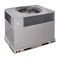
C. ROUTING AND SUSPENDING REFRIGERANT LINES
Run refrigerant lines as straight and direct as possible, avoiding
unnecessary bends and turns. Always insulate the entire suction
line. Both lines should be insulated when routed through an attic or
when routed through an underground raceway.
When routing refrigerant lines through a foundation or wall, do not
allow refrigerant lines to come in direct contact with the building
structure. Make openings large enough so that lines can be
wrapped with extra insulation. Fill all gaps with RTV caulk. This
will prevent noise transmission between the tubing and the
foundation or wall.
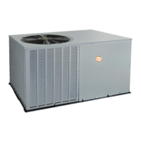
Along floor or ceiling joists, suspend refrigerant lines so that they
do not contact the building structure, water pipes, or ductwork. Use
insulated or suspension type hangers. Metal straps must be at least
1” (25 mm) wide to avoid cutting into the tube insulation. Keep the
liquid and suction lines separate. Refer to Fig. 3.
INSULATION
SUCTION TUBE
LIQUID TUBE
OUTDOOR WALL INDOOR WALL
LIQUID TUBE
SUCTION TUBE
INSULATION
CAULK
HANGER STRAP
(AROUND SUCTION
TUBE ONLY)
JOIST
1” MIN
THROUGH THE WALL
SUSPENSION
A07588
Fig. 3 --- Routing and Suspending Refrigerant Lines