6
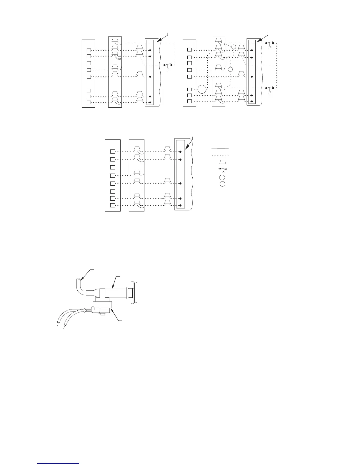
LEGEND
24 V FACTORY WIRING
24 V FIELD WIRING
FIELD SPLICE CONNECTION
OUTDOOR THERMOSTAT
EMERGENCY HEAT RELAY
SUPPLEMENTAL HEAT RELAY
SHR
EHR
C
W
2
L
G
Y
E
O
R
C
W
2
L
G
Y
E
O
R
ODT
EHR
ODT
ODT
REMOVE WIRES FROM CRIMP NUT IN INDOOR FAN COIL WHEN INSTALLING OUTDOOR THERMOSTATS.
SYSTEMS WITH ONE OUTDOOR THERMOSTAT
G
R
W
3
C
O
R
G
R
W
3
C
E
C
W
2
Y
W
2
O
R
C
W
2
Y
W
2
C
L
G
Y
E
O
R
SYSTEMS WITHOUT OUTDOOR THERMOSTATS
C
G
R
W
2
C
Y
O
R
W
2
SUBBASE
THERMOSTAT
CONNECTION
SPLICE
INDOOR
CONNECTION
SPLICE
OUTDOOR
BOARD
DEFROST
SUBBASE
THERMOSTAT
CONNECTION
SPLICE
INDOOR
CONNECTION
SPLICE
OUTDOOR
BOARD
DEFROST
SUBBASE
THERMOSTAT
CONNECTION
SPLICE
INDOOR
CONNECTION
SPLICE
OUTDOOR
BOARD
DEFROST
SYSTEMS WITH TWO OUTDOOR THERMOSTATS
NOTE: WHEN USING OUTDOOR THERMOSTATS, W
2
MUST BE ENERGIZED WHEN REQUESTING SUPPLEMENTAL HEAT.
W
2
E
SHR
SHR
A07595
Fig. 7 --- T ypical Thermostat (Control Circuit) Connections
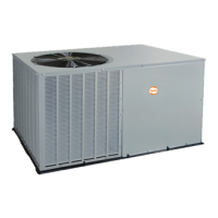
DEFROST SYSTEM
A. DEFROST THERMOSTAT
The defrost thermostat is factory installed on a short tube stub
extending from the coil end plate. Refer to Fig. 8 and confirm that
the thermostat is securely fastened in place on the tube stub.
FEEDER TUBE
TUBE STUB
DEFROST
THERMOSTAT
COIL
A07596
Fig. 8 --- Defrost Thermostat
B. DEFROST CONTROL BOARD
The defrost board is a time/temperature control which includes a
field--selectable time period between defrost cycles of 30, 60, or 90
minutes (quick--connects located at board edge, factory set at 90
minutes).
Defrost mode is identical to cooling mode except that outdoor-- fan
motor stops and second--stage heat is turned on to continue
warming conditioned space.
Initially, the defrost cycle timer starts when the contactor is
energized and a 24 VAC signal is present on the T1 terminal. Then
the defrost cycle begins when the defrost thermostat is closed and
the cycle timer times out (30, 60, 90 or minutes).
To initiate a forced defrost cycle, the defrost thermostat must be
closed. This can be accomplished as follows:
1. Turn off power to outdoor unit.
2. Disconnect outdoor fan--motor lead from OF2 on control
board (refer to Fig. 9). Tape lead to prevent grounding.
3. Restart unit in heating mode, allowing frost to accumulate
on outdoor coil.
4. After a few minutes in heating mode, liquid line
temperature should drop below closing point of defrost
thermostat (approximately 32_F/0_C).
5. Short between speed--up terminals with a flat-- bladed
screwdriver (refer to Fig. 9). This reduces the timing
sequence to 7, 14, or 21 seconds (30, 60, or 90 minute
defrost selection, respectively).
6. When you hear reversing valve change position, remove
screwdriver immediately; otherwise, control will terminate
normal 10-- minute defrost cycle in approximately 2
seconds.
NOTE: Length of defrost cycle is dependent upon length of time
it takes to remove screwdriver from test pins after reversing valve
has shifted.
7. Unit will remain in defrost for remainder of defrost-- cycle
time or until defrost thermostat reopens at approximately
65_F/18_C coil temperature of liquid line.
8. Turn off power to outdoor unit and reconnect fan-- motor
lead to OF2 on control board (refer to Fig. 9).