5
Line set and indoor coil should be evacuated using the
recommended deep vacuum method of 500 microns. If deep
vacuum equipment is not available, the alternate triple evacuation
method may be used by following the specified procedure.
If vacuum must be interrupted during the evacuation procedure,
always break vacuum with dry nitrogen.
Deep Vacuum Method
The deep vacuum method requires a vacuum pump capable of
pulling a vacuum to 500 microns and a vacuum gauge capable of
accurately measuring this vacuum level. The deep vacuum method
is the most positive way of assuring a system is free of air and
water.
Watch the vacuum gauge as the system is pulling down. The
response of the gauge is an indicator of the condition of the system.
With no leaks in the system, allow the vacuum pump to run for 30
minutes minimum at the deep vacuum level.
Triple Evacuation Method
The triple evacuation method should only be used when system
does not contain any water in liquid form and vacuum pump is
only capable of pulling down to 28 inches (711 mm) of mercury.
Proceed as follows:
1. Pull system down to 28 inches (711 mm) of mercury and
allow pump to continue operating for an additional 15
minutes.
2. Close manifold valves or valve at vacuum pump and shut
off vacuum pump.
3. Connect a nitrogen cylinder and regulator to system and fill
with nitrogen until system pressure is 2 psig.
4. Close nitrogen valve and allow system to stand for 1 hour.
During this time, dry nitrogen will diffuse throughout the
system absorbing moisture.
5. Repeat this procedur.
6. After the final evacuate sequence, confirm there are no leaks
in the system. If a leak is found, repeat the entire process
after repair is made.
I. OPENING SERVICE VALVES
Outdoor units are shipped with a refrigerant charge sealed in the
unit. Opening the service valves releases this charge into the
system.
NOTE: Open the Suction service valve first. If the Liquid service
valve is opened first, oil from the compressor may be drawn into
the indoor coil TXV, restricting refrigerant flow and affecting
operation of the system.
Remove Suction service valve cap and insert a hex wrench into the
valve stem. Hold the valve body steady with an end --wrench and
back out the stem by turning the hex wrench counterclockwise.
Turn the stem until it just contacts the rolled lip of the valve body.
After the refrigerant charge has bled into the system, open the
Liquid service valve.
NOTE: These are not back -- seating valves. It is not necessary to
force the stem tightly against the rolled lip.
The service valve cap is a primary seal for the valve and must be
properly tightened to prevent leaks. Make sure cap is clean and
apply refrigerant oil to threads and sealing surface on inside of cap.
Tighten cap finger tight and then tighten additional 1/6 of a turn (1
wrench flat) to properly seat the sealing surfaces.
J. GAUGE PORTS
Check for leaks at the schrader ports and tighten valve cores if
necessary. Install plastic caps finger tight.
ELECTRICAL WIRING
ELECTRICAL SHOCK HAZARD
Failure to turn off the main (remote) electrical disconnect
device could result in personal injury or death.
Before installing, modifying or servicing system, turn OFF
the main (remote) electrical disconnect device. There may be
more than one disconnect device.
!
WARNING
The supply voltage must be 208/230 volts (197 volt minimum to
253 volts maximum) 60 Hz single phase.
Outdoor units are approved for use with copper conductors only.
Do not use aluminum wire.
Refer to unit rating plate for minimum circuit ampacity and circuit
protection requirements.
Grounding
Permanently ground unit in accordance with the National Electrical
Code and local codes or ordinances. Use a copper conductor of the
correct size from the grounding lug in control box to a grounded
connection in the service panel or a properly driven and electrically
grounded ground rod.
Wiring Connections
Make all outdoor electrical supply (Line Voltage) connections with
rain--tight conduit and fittings. Most codes require a disconnect
switch outdoors within sight of the unit. Consult local codes for
special requirements.
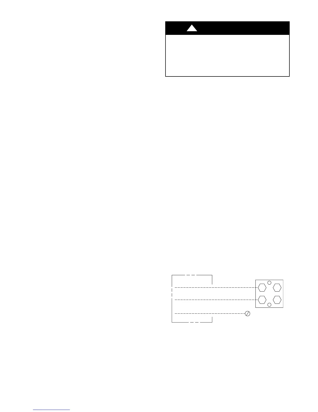
Route electrical supply (Line Voltage) wiring through knockout
hole in bottom of Control Box. Connect wires to Contactor and
Ground Lug according to Wiring Diagram on unit. Also refer to
Fig. 6.
Route thermostat wiring through rubber grommet in bottom of
Control Box. Low voltage lead wires are provided in the control
box for connection to thermostat wires (use wire nuts). Refer to
Wiring Diagram on unit and Fig. 7 for low voltage wiring
examples.
NOTE: Use No. 18 AWG (American Wire Gage) color-- coded,
insulated (35˚C minimum) wire. If thermostat is located more than
100 feet (30.5 m) from unit as measured along the control voltage
wires, use No. 16 AWG color--coded wires to avoid excessive
voltage drop.
DISCONNECT
PER N. E. C. AND/OR
LOCAL CODES
CONTACTOR
GROUND
LUG
FIELD GROUND
WIRING
FIELD POWER
WIRING
A91056
Fig. 6 --- Electrical Supply (Line Voltage) Connections
 Loading...