7
R8
OF1
K1
O1
R21
C2
R6
H9C1
C US
R14
R13
D13
R7
C4
C10
JW2
JW1
D3
C16
C7
R28
D6
JW3
C13
R4
R1
R2
R3
R11
R5
R26
D1
D2
D10
A29
R9
D4
C19
C9
C1
OF2
CEBD430524 01A 5501A
P2
1
Y
T1 C C O
DFT
SPEEDUP
P1
1
J1
1
P3
1
J2
30 60 90
W1
R20
1
HK32EA001
C17
U1
1
U3
O
R
W
2
Y
C
A07597
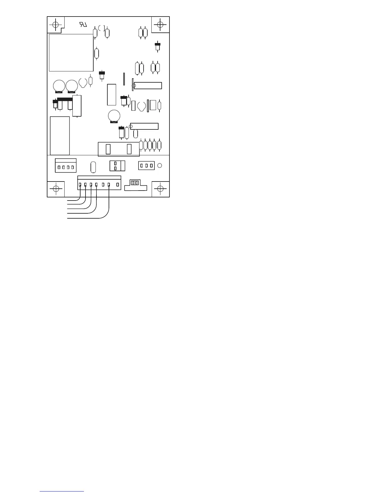
Fig. 9 --- Defrost Control Board
START--UP PROCEDURE
1. Set indoor thermostat selector switch to OFF.
2. Turn ON all electrical disconnect devices.
3. If unit has a crankcase heater, ener gize the heater and wait
24 hours before proceeding.
4. Set indoor thermostat at desired temperature. Be sure
setpoint is below indoor ambient temperature or thermostat
will not call for cooling.
5. Set indoor thermostat selector switch to COOL or HEAT.
Operate unit for minimum 10 minutes, then check the
system refrigerant charge.
REFRIGERANT CHARGE
A. COOLING MODE
Outdoor units are shipped with a refrigerant charge to match a
specific indoor coil and 15 feet (4.6 m) of refrigerant line. If
shorter or longer refrigerant lines or a different indoor coil are used,
the charge will have to be adjusted.
For different line lengths, add or remove charge based on 0.6
ounces charge per foot of difference. For example, a 25 foot (7.6
m) line set is 10 feet (3 m) longer than the specified 15 feet (4.6 m).
Add 0.6 ounces charge for each of the extra 10 feet (3 m):
10 x 0.6 = 6.0 ounces additional charge
This outdoor unit is designed for use only with indoor coils that
utilize a hard shut--off TXV refrigerant metering device. With a
hard shut--off indoor TXV, use the subcooling method to make
final charge adjustments:
1. Operate unit a minimum of 10 minutes before checking
charge.
2. Measure liquid service valve pressure by attaching an
accurate gauge to service port.
3. Measure liquid line temperature by attaching an accurate
thermistor type sensor or electronic thermometer to liquid
line near outdoor coil.
4. Refer to unit rating plate for required subcooling
temperature.
5. Refer to Table 2. Find the required liquid line temperature
where the rating plate subcooling temperature intersects
measured liquid service valve pressure.
6. If the measured liquid line temperature is higher than the
chart number, add refrigerant to lower the measured
temperature.
NOTE: When adding refrigerant, charge in liquid form, using a
flow restricting device, into the suction port. If the measured liquid
line temperature is lower than the chart number, reclaim refrigerant
to raise the measured temperature. Tolerance is ±3˚F/1.65˚C.
B. HEATING MODE
To check system operation during heating cycle, refer to the Tech
Label on outdoor unit. This chart indicates whether a correct
relationship exists between system operating pressure and air
temperature entering indoor and outdoor units. If pressure and
temperature do not match on chart, system refrigerant charge may
not be correct. Do not use chart to adjust refrigerant charge.
NOTE: When charging is necessary during heating season, charge
must be weighed in accordance with unit rating plate ±0.6 ounces
per foot of 3/8 inch liquid line above or below 15 feet (4.6 m)
respectively.