4
UNIT OPERATION HAZARD
Failure to follow this caution may result in improper
product operation.
Do not bury more than 36” (914 mm) of line set
underground. Refrigerant may migrate to cooler buried
section during extended periods of unit shut-- down, causing
refrigerant slugging and possible compressor damage at
start--up.If ANY section of the line set is buried
underground, provide a minimum 6” (152 mm) vertical rise
at the service valve.
CAUTION
!
D. OUTDOOR UNIT HIGHER THAN INDOOR UNIT
Proper oil return to the compressor should be maintained with
suction gas velocity. If velocities drop below 1500 fpm (feet per
minute), oil return will be decreased. To maintain suction gas
velocity , do not upsize vertical suction risers. Use the “<80 feet (24
m)” suction line sizes shown Table 1.
Install oil traps every 20 feet (6 m) of vertical suction line riser .
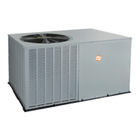
E. LIQUID LINE FILTER --DRIER
Outdoor units are shipped with an appropriate filter--drier for
installation in the liquid line. Leave the plugs in the tube ends until
the filter--drier is installed. The optimal location for the filter--drier
is close to the indoor coil. Install the filter--drier with the arrow
pointing towards the indoor coil. Refer to Fig. 4.
A05227
Fig. 4 --- Liquid Line Filter Drier Installed at Indoor Coil
F. SERVICE VALVES
Service valves are closed and plugged from the factory. Outdoor
units are shipped with a refrigerant charge sealed in the unit. Leave
the service valves closed until all other refrigerant system work is
complete or the charge will be lost. Leave the plugs in place until
line set tubing is ready to be inserted.
Heat pumps require a piston metering device in the liquid service
valve for proper heating operation. Piston is shipped in the piston
body of the liquid service valve, temporarily held in place with a
plastic cap. Do not remove the plastic cap until line set tubing is
ready to be installed.
Refer to Fig. 5 and follow these steps for piston installation:
1. Remove plastic cap holding piston in piston body of liquid
service valve.
2. Check that piston size (stamped on side of piston) matches
with number listed on unit rating plate. Return piston to
piston body of liquid service valve (either direction).
3. Find plastic bag taped to unit containing copper adapter
tube, brass nut, and plastic washer.
4. Install plastic washer in the seat inside piston body.
5. Fit brass nut onto adapter tube and install tube onto liquid
service valve. Tighten nut finger tight, then wrench
additional half turn only. Over tightening may damage the
plastic washer.
Service valve bodies are brass and suction tube stub is copper.
PISTON BODY
LIQUID SERVICE VALVE
PISTON
PLASTIC WASHER
ADAPTER TUBE
BRASS NUT
A07594
Fig. 5 --- Liquid Service Valve with Piston and Adapter Tube
G. BRAZING CONNECTIONS
FIRE HAZARD
Failure to follow this warning could result in personal injury,
death, and/or property damage.
Refrigerant and oil mixture could ignite and burn as it
escapes and contacts brazing torch. Make sure the refrigerant
charge is properly removed from both the high and low sides
of the system before brazing any component or lines.
!
WARNING
Clean line set tube ends with emery cloth or steel brush. Remove
any grit or debris.
Insert line set tube ends into service valve tube stubs.
Apply heat absorbing paste or heat sink product between service
valve and joint. Wrap service valves with a heat sinking material
such as a wet cloth.
Braze joints using a Sil--Fos or Phos--copper alloy.
PRODUCT DAMAGE HAZARD
Failure to follow this caution may result in product damage.
Braze with Sil--Fos or Phos--copper alloy on
copper--to--copper joints and wrap a wet cloth around rear
of fitting to prevent damage to TXV.
CAUTION
!
H. EVACUATING LINE SET AND INDOOR COIL
The unit is shipped with a factory refrigerant charge. The liquid
line and suction line service valves have been closed after final
testing at the factory. Do not disturb these valves until the line set
and indoor coil have been evacuated and leak checked, or the
charge in the unit may be lost.
NOTE: Do not use any portion of the factory charge for purging
or leak testing. The factory charge is for filling the system only
after a complete evacuation and leak check has been performed.
PRODUCT DAMAGE HAZARD
Failure to follow this caution may result in product damage.
Never use the outdoor unit compressor as a vacuum pump.
Doing so may damage the compressor.
CAUTION
!