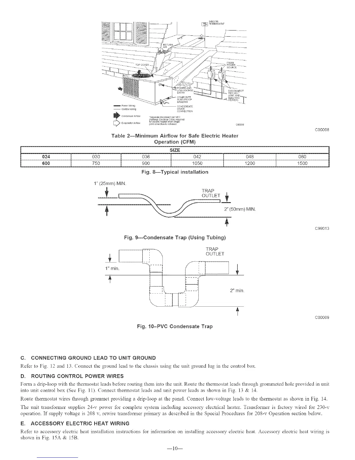
FROM
POWER
77 SOURCE
1
I
024 030
600 750
pu_erW)ring
--¢ontroIWidng
"Separated_sconnectpe_NEC
@Na_ol_alElec_r4calCode required
breec rchea erwhen snge
_n_conection isnot used
Table 2--Minimum Airflow for Safe Electric Heater
Operation (CFM)
SIZE
036 ] 042 l900 1050
Fig, 8--Typical installation
048
1200
1_'(25ram) MtN.
TRAP
2" (50mm) MiN.
Fig. 9--Condensate Trap (Using Tubing)
1" rain.
TRAP
OUTLET
T
C00008
060 1
1500
C99013
Fig. 10-PVC Condensate Trap
C00009
C. CONNECTING GROUND LEAD TO UNiT GROUND
Refer to Fig 12 and 13_ (onnect the ground lead to the chassis using the unit ground tug in the control box
D. ROUTING CONTROL POWER WIRES
Form a drip-loop with the thermostat leads before routing them into the unit Route the thermostat leads through grommeted hole provided in unit
into unit control box (See Fi b 11). Connect thermostat leads and unit power leads as shown in Fig. 13 & 14.
Route thermostat wires through grommet providing a drip-loop at the panel Connect low-voltage leads to the thermostat as shown in Fig. 14.
The unit transformer supplies 24-v power fbr complete system including accessory electrical heater. Transfbm_er is _actory wired t'or 230-v
operation. If supply voltage is 208 v, rewire tran@ormer primary as described in the Special Procedures for 208-v Operation section below.
E. ACCESSORY ELECTRIC HEAT WIRING
Re_r to accesso_- electric heat installation instructions for infom_ation on installing accesso_" electric heat Accesso_" electric heat wiring is
shown in Fig. 15A & 15B.
i0