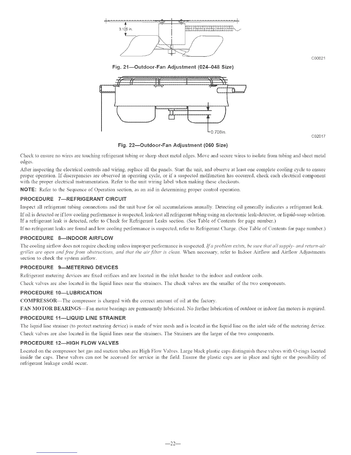
Fig. 21--Outdoor-Fan Adjustment (024=048 Size)
C00021
C02017
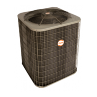
Fig. 22--OutdooroFan Adjustment (060 Size)
(beck to ensure no wires are touching refrigerant tubing o1"sharp sheet metal edges Move and secure wires to isolate fi'om robing and sheet metal
edges
After inspecting the electrical controls and wiring, replace all the panels Start the unit, and observe at least one complete cooling cycle to ensure
proper operatiom If discrepancies are observed in operating cycle, or if a suspected multi.ruction has occurre& check each electIical component
with the proper electrical instrumentation. Refer to the unit wiring label when making these checkouts.
NOTE: Refer to the Sequence of Operation section, as an aid in determining proper control operation.
PROCEDURE 7--REFRIGERANT CIRCUIT
Inspect all re_'rigerant robing connections and the unit base fbr oil accumulations annually Detecting oil generally indicates a refi'igerant leaL
If oil is detected or if low cooling perfbrmaace is suspected, leak=test all refi'igeraat tubing using an electronic leak-detector, or liquid-soap solution.
If a refrigerant leak is detected, refer to Check fbr Refrigerant Leaks section. (See Table of Contents f'or page number.)
If no refi'igerant leaks are found and low cooling performance is suspected, refer to Refi'igerant Charge. (See Table of Contents for page number.
PROCEDURE 8--_NDOOR ABRFLOW
The cooling airflow does not require checking unless improper perfbrmance is suspected Ira problem _:visL_'.be .sw'e that all_@id3'- cmd return-an'
grgles are open and fi'eefi'om ob.str_ctio_v.s, as_d that the air filter i.s c/c-as_. When necessa_', refer to Indoor Airflow and Airflow Adjustments
section to check the system airflow.
PROCEDURE 9--METERmNG DEVBCES
Refrigerant metering devices are f_xed orifices and are located in the inlet header to [!_e indoor and outdoor coils
Check valves are also located in the liquid lines near the strainers. The check valves are the smaller of the two components.
PROCEDURE 10--LUBR_CATmON
COMPRESSO_The compressor is charged with the correct amount of oil at the £hctory
FAN MOTOR BEARINGS Fan motor bearings are pem_anently lubricated. No further lubrication of outdoor or indoor fun motors is required.
PROCEDURE 11--LBQUID UNE STRAINER
7he liquid line strainer (to protect metering device) is made of wire mesh and is located in the liquid line on the inlet side of the meteiing device.
(beck valves are also located in the liquid lines near the stlainers. The Stlainers are the larger of the two components.
PROCEDURE 12--HGH FLOW VALVES
Located on the compressor hot gas and suction tubes are High Flow Valves. Large black plastic caps distinguish these valves with ()-rings located
inside the caps. These valves can not be accessed for service in the field. Ensure the plastic caps are in place and tight or the possibility of
refrigerant leakage could occur.
22