LEGEND
FLA -- Fult Load Amps
LRA -- Locked Rotor Amps 1,_
MCA -- Minimum Circuit Amps
MOCP -- Maximum Overcurrent Protection
RLA -- Rated Load Amps
CKT BKR -- Circuit Breaker
NOTES:
1. In compliance with NEC (National Electrical Code) requirements
for multimotor and combination toad equipment (refer to NEC
Articles 430 and 440), the overcurrent protective device for the
unit shall be Power Supply fuse. Canadian units may be
fuse or circuit breaker.
2. Minimum wire size is based on 60 C copper wire. If other than
60 C wire is used, or if tength exceeds wire length in table,
determine size from NEC.
3. Unbalanced 3-Phase Supply Voltage
Never operate a motor where a phase imbalance in supply volt-
age is greater than 2%. Use the following formula to determine
the percentage of voltage imbalance.
% Voltage imbalance
= 100 x max vottage deviation from average voltage
average vottage
EXAMPLE: Supply voltage is 460-3-60.
A B C AB = 452 v
BC = 464 v
AC = 455 v
Average Voltage =
452 + 464 + 455
3
1371
3
= 457
Determine maximum deviation from average voltage.
(AB) 457 452=5v
(BC) 464 457=7v
(AC) 457 455=2v
Maximum deviation is 7 v.
Determine percent of 'voltage imbalance.
7
% Voltage Imbalance = 100 x --
457
= 1.53%
This amount of phase imbalance is satisfactory as it is below the
maximum allowable 2%.
IMPORTANT: If the supply voltage phase imbalance is
more than 2%, contact your local etectric utility company
immediate@.
c99024
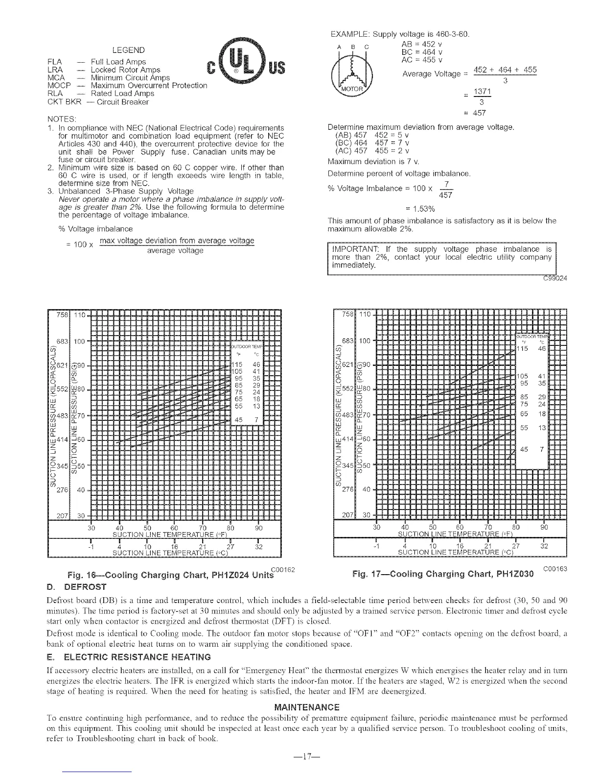
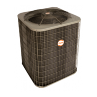
4O 5O
SUCTION LINE TEMPERATURE
| JJ m J m| Jm J B m |J |HI
3O
30 40 50 60
SUCTION LINE TEMPERATURE i
70 80 90
4 10 16 21 27 32
SUCTION LINE TEMPERATURE i
Fig. 16--Cooling Charging Chart, PHIZ024 Units c00162 Fig. 17--Cooling Charging Chart, PHIZ030 c00163
D. DEFROST
Defi'ost board (DB) is a time and temperature control, which includes a fiekl-selectable time period between checks for defrost (30, 50 and 90
minutes). The time period is [hctory=set at 30 minutes and should only be adjusted by a trained service person. Electronic timer and defi'ost cycle
start only when contactor is energized and defrost thermostat (DFT) is closed.
Del:i'ost mode is identical to Cooling mode. The outdoor fan motor stops because of "OFF' and "OFT' contacts opening on the deJi'ost board, a
bank of optional electric heat turns on to warm air supplying the conditioned space.
E. ELECTRIC RESISTANCE HEATmNG
If accesso! 2- electric heaters are installed, on a call _i_)r"Emergency Heat" the thermostat energizes W which energises the heater relay and in turn
energizes the electric heaters. The IFR is energized which starts the indoor-fan motor. If the heaters are stage& W2 is energized when the second
stage of heating is required. When the need for heating is satisfied, the heater and IFM are deenergized.
MAINTENANCE
To ensure continuing high perfbm_ance, and to reduce the possibility of prenmmre eqtdpment failure, periodic nmintenance must be performed
on this equipment. This cooling unit should be inspected at least once each year by a qualified sela'ice person. To troubleshoot cooling of units,
refer to Troubleshooting chart in back of book.
17