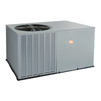
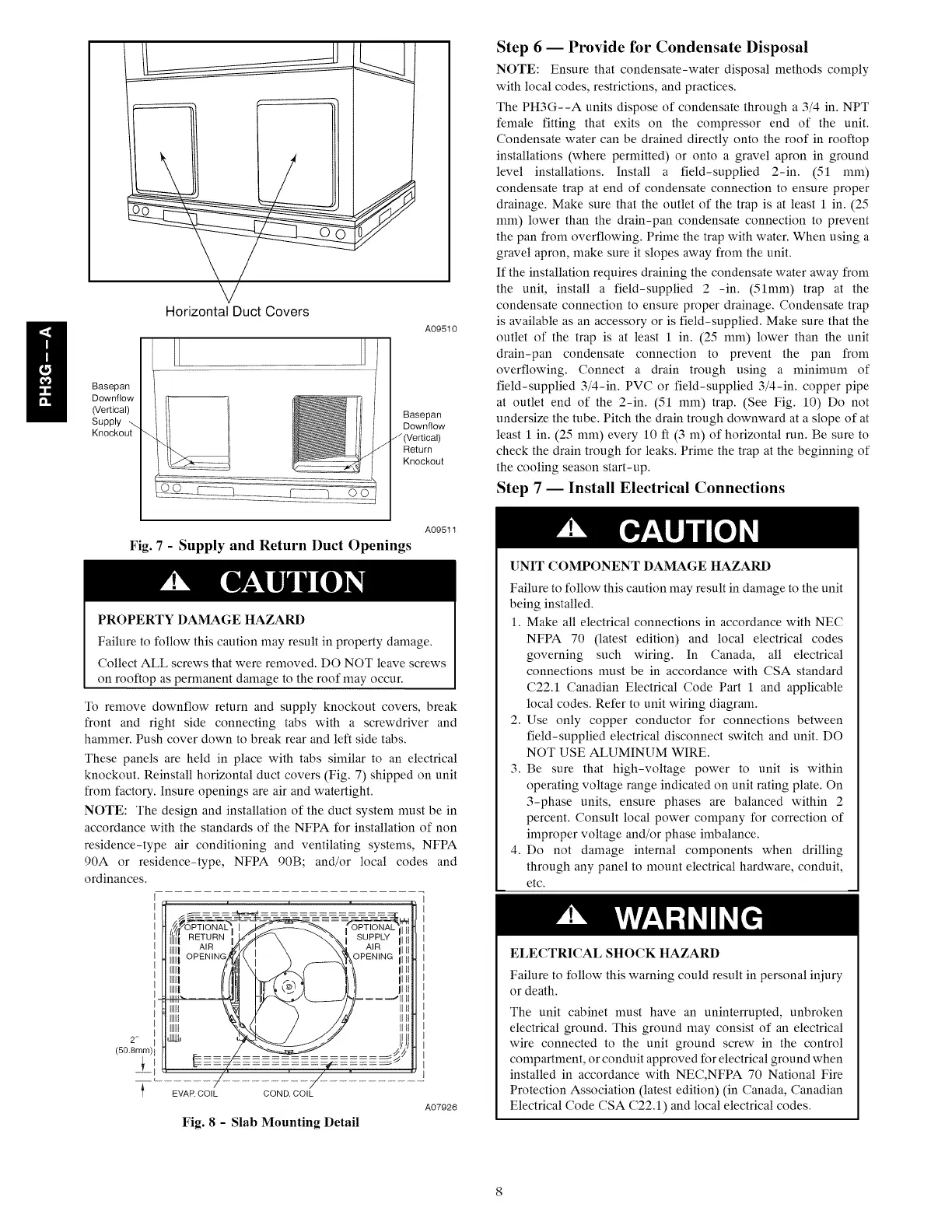
Basepan
Downflow
(Vertical)
Supply _.
Knockout
Horizontal Duct Covers
/
A09510
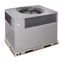
Basepan
Downflow
/ (Vertical)
Return
Knockout
Step 6 -- Provide for Condensate Disposal
NOTE: Ensure that condensate-water disposal methods comply
with local codes, restrictions, and practices.
The PH3G--A units dispose of condensate through a 3/4 in. NPT
female fitting that exits on the compressor end of the unit.
Condensate water can be drained directly onto the roof in rooftop
installations (where permitted) or onto a gravel @ron in ground
level installations. Install a field-supplied 2-in. (51 mm)
condensate trap at end of condensate connection to ensure proper
drainage. Make sure that the outlet of the trap is at least I in. (25
mm) lower than the drain-pan condensate connection to prevent
the pan from overflowing. Prime the trap with water. When using a
gravel @ron, make sure it slopes away from the unit.
If the installation requires draining the condensate water away from
the unit, install a field-supplied 2 -in. (51mm) trap at the
condensate connection to ensure proper drainage. Condensate tr@
is available as an accessory or is field-supplied. Make sure that the
outlet of the tr@ is at least I in. (25 mm) lower than the unit
drain-pan condensate connection to prevent the pan from
overflowing. Connect a drain trough using a minimum of
field-supplied 3/4-in. PVC or field-supplied 3/4-in. copper pipe
at outlet end of the 2-in. (51 mm) tr@. (See Fig. 10) Do not
undersize the tube. Pitch the drain trough downward at a slope of at
least 1 in. (25 mm) every 10 ft (3 m) of horizontal run. Be sure to
check the drain trough for leaks. Prime the trap at the beginning of
the cooling season start-up.
Step 7 -- Install Electrical Connections
A09511
Fig. 7 - Supply and Return Duct Openings
PROPERTY DAMAGE HAZARD
Failure to follow this caution may result in property damage.
Collect ALL screws that were removed. DO NOT leave screws
on rooftop as permanent damage to the roof may occur.
To remove downflow return and supply knockout covers, break
front and right side connecting tabs with a screwdriver and
hammer. Push cover down to break rear and left side tabs.
These panels are held in place with tabs similar to an electrical
knockout. Reinstall horizontal duct covers (Fig. 7) shipped on unit
from factory. Insure openings are air and watertight.
NOTE: The design and installation of the duct system must be in
accordance with the standards of the NFPA for installation of non
residence-type air conditioning and ventilating systems, NFPA
90A or residence-type, NFPA 90B; and/or local codes and
ordinances.
I
2"* I
(50.8ram) I
±,,
EVAR COIL COND. COIL
Fig. 8 - Slab Mounting Detail
A07926
UNIT COMPONENT DAMAGE HAZARD
Failure to follow this caution may result in damage to the unit
being installed.
1. Make all electrical connections in accordance with NEC
NFPA 70 (latest edition) and local electrical codes
governing such wiring. In Canada, all electrical
connections must be in accordance with CSA standard
C22.1 Canadian Electrical Code Part 1 and applicable
local codes. Refer to unit wiring diagram.
2. Use only copper conductor for connections between
field-supplied electrical disconnect switch and unit. DO
NOT USE ALUMINUM WIRE.
3. Be sure that high-voltage power to unit is within
operating voltage range indicated on unit rating plate. On
3-phase units, ensure phases are balanced within 2
percent. Consult local power company for correction of
improper voltage and/or phase imbalance.
4. Do not damage internal components when drilling
through any panel to mount electrical hardware, conduit,
etc.
ELECTRICAL SHOCK HAZARD
Failure to follow this warning could result in personal injury
or death.
The unit cabinet must have an uninterrupted, unbroken
electrical ground. This ground may consist of an electrical
wire connected to the unit ground screw in the control
compartment, or conduit approved for electrical ground when
installed in accordance with NEC,NFPA 70 National Fire
Protection Association (latest edition) (in Canada, Canadian
Electrical Code CSA C22.1) and local electrical codes.
 Loading...