11
Chapter 2: Motherboard Installation
SPK1: Speaker Header
Connect the cable from the PC speaker to the SPK1 header on the motherboard.
AUDIO1: Front Panel Audio Header
This header allows the user to install auxiliary front-oriented microphone and
line-out ports for easier access.
USB2/USB3: Front panel USB Header
The motherboard has USB ports installed on the rear edge I/O port array.
Additionally, some computer cases have USB ports at the front of the case. If
you have this kind of case, use auxiliary USB headers USB2/USB3 to connect
the front-mounted ports to the motherboard.
Pin Signal
1SPKR
2NC
3GND
4+5V
Pin Signal Pin Signal
1 AUD_MIC 2 A UD_GND
3 AUD_MIC_BIAS 4 AUD_V CC
5 AUD_FPOUT_R 6 A UD_RET_R
7 HP_ ON 8 KEY
9 AUD_FPOUT_L 10 AUD_RET_L
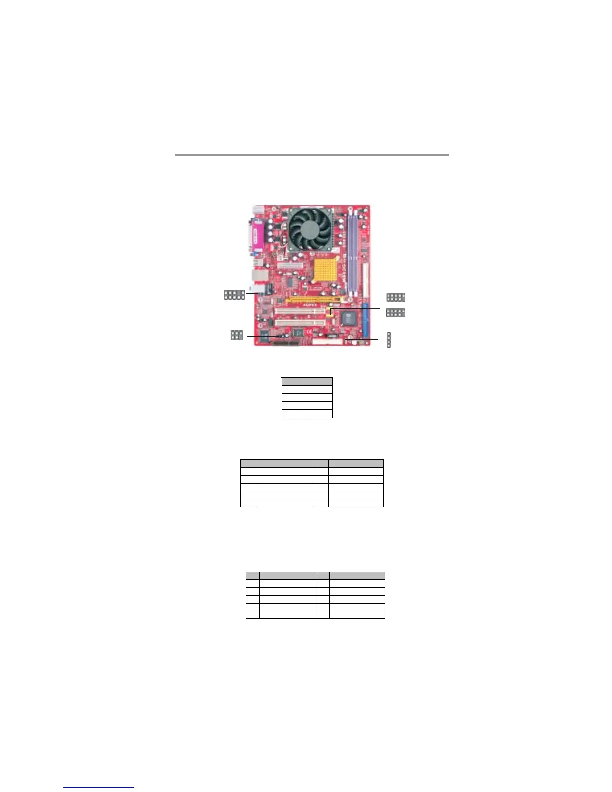
Connecting Optional Devices
Refer to the following for information on connecting the motherboard’s optional
devices:
AUDIO1
1
Pin Signal Pin Signal
1 VERG_FP_USBPWR0 2 VERG_FP_USBPWR0
3 USB_FP_P0(-) 4 USB_FP_P1(-)
5 USB_FP_P0(+) 6 USB_FP_P1(+)
7 GROUND 8 GROUND
9 KEY 10 USB_FP_OC0
SPK1
1
1
USB3
1
USB2
IR1
1