EasyManua.ls Logo

PDA Range PDA200/2 User Manual

PDA Range PDA200/2
16 pages
To Next Page IconTo Next Page
Page #1 background imageLoading...
Page #1 background image
PDA Pro-Range Instructions • Approved Doc. No. DCP0003168 Rev 1 • Page 1
PDA200/2, PDA500/2, PDA1000/2
INSTALLATION INSTRUCTIONS
This equipment must be installed by a suitably skilled and technically
competent person. Please read these instructions carefully before installation.
Important notes .......................................................................................... 2
What is an audio frequency induction loop system? .............................. 3
Familiarisation with your PDA Pro-Range induction loop amplifier ..... 4
Planning the system .................................................................................. 6
Overview of the ‘Outreach plate’ audio input extension system .......... 7
A typical PDA Pro-Range induction loop system .................................... 8
Installation ................................................................................................... 11
Safety precautions ..................................................................................... 11
Mounting the amplifier .............................................................................. 11
Connecting and testing the system ......................................................... 12
Technical specification .............................................................................. 14
Spares and accessories .............................................................................. 16
PROFESSIONAL AUDIO-FREQUENCY
INDUCTION LOOP AMPLIFIERS
O
U
T
R
E
A
C
H
C
O
M
P
A
T
I
B
L
E
Question and Answer IconNeed help?

Do you have a question about the PDA Range PDA200/2 and is the answer not in the manual?

PDA Range PDA200/2 Specifications

General IconGeneral
BrandPDA Range
ModelPDA200/2
CategoryAmplifier
LanguageEnglish

Summary

Important Notes and Safety Precautions

Installation Responsibility and Liability

States the amplifier must be installed by a skilled person; manufacturer is not liable for misinterpretation.

Critical Operation Warning

Crucial warning that the amplifier must never be operated without a loop connected to it.

Familiarisation with Your Pro-Range Amplifier

Input Mode Select Switches

Explains the function of the input mode select switches for configuring inputs and phantom power.

Front Panel Controls and Indicators

Amplifier Model and Core Controls

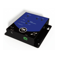
Details the model number and the purpose of the Loop Drive and Metal Compensation controls.

Status Indicators

Describes the meaning of the power indicator, loop strength meter, and compression indicators.

System Planning and Loop Installation

Area of Coverage and Cable Selection

Provides guidance on maximum coverage areas and selecting appropriate cable CSA based on length.

Installation Procedures

Installation Safety Precautions

Outlines safety measures regarding environment, dismantling, and securing cables before operation.

Connecting and Testing the System

Pre-Power Up Checks

Includes crucial steps like installing the loop, checking for shorts, and connecting inputs.

Input Signal Level Adjustment

Guides on adjusting input level controls for optimal compression indicator response.

Loop Drive and Signal Strength

Details how to adjust the DRIVE control and use the loop strength meter for consistent coverage.

Metal Compensation Control

Technical Specifications

Power and Input/Output Details

Provides specifications for power consumption, input impedances, sensitivities, and output types.

Amplifier Features and Dimensions

Related product manuals