PDA Pro-Range Instructions • Approved Doc. No. DCP0003168 Rev 1 • Page 12
8
9
7
10
The loop strength meter’s red peak indicator (the fifth LED on the gauge)
should only illuminate with peaks in the input signal - if it is lit too
frequently, the audio sound quality will be distorted and the amplifier may
overheat. If this is the case, try adjusting the layout of the loop and/or consider
purchasing a more powerful PDA range amplifier.
If it is impossible to illuminate all of the indicators on the loop strength
meter even when the
DRIVE
control is turned fully clockwise, the thickness
(CSA) of the induction loop cable used may be insufficient for the job.
Please refer to Loop cable selection, page 6, to ensure you are using the
recommended cable for the application.
6
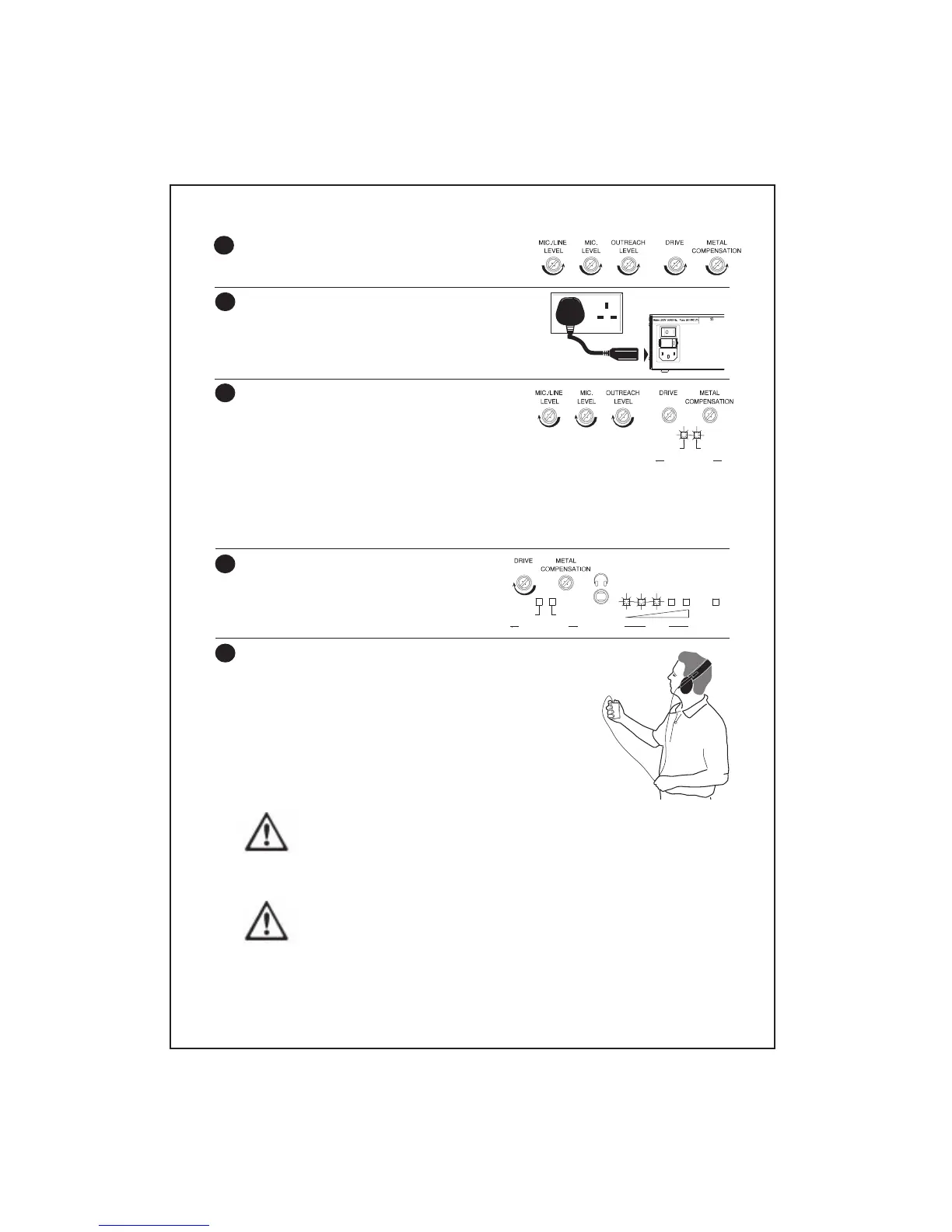
Ensure the amplifier’s
DRIVE, METAL COMPENSATION
and three
LEVEL
controls are set to minimum by
turning them fully anti-clockwise.
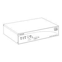
Connect the AC power lead (supplied) to a 230V a.c.
wall socket and the amplifier‘s 230V socket as
shown, flick the rocker switch to the on (I) position
and ensure the amplifier’s red
POWER
indicator is
lit.
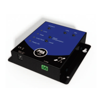
With all relevant audio input source(s) active,
increase the appropriate
LEVEL
controls until the
LOW
compression indicator is lit most of the time
and the
HIGH
compression indicator illuminates
with peaks in the input signal(s).
Note that it is perfectly acceptable for the
HIGH
indicator to be lit two thirds of the
time but not for them to be permanently lit.
TIP: If you are using the mic., mic./line and outreach input at the same time, adjust the
level control on each outreach plate to achieve an acceptable balance.
Adjust the
DRIVE
control by turning it
clockwise until the first three lights on the
amplifier’s loop strength meter start to
illuminate.
Using an induction loop listening device, listen to the loop signal
in the centre of the loop. If the signal level is not acceptable,
adjust the
DRIVE
control in small increments until it is.
When you are satisfied with the signal in the centre of the
loop, move around the room to ensure coverage is consistent
throughout.
Pay particular attention to areas where hearing aid users are
likely to gather and take note of the following warning and
advice tips:-
COMPRESSION
LOW
HIGH
COMPRESSION
LOW
HIGH
DRIVE
POWER
continued on page 13