PDA Pro-Range Instructions • Approved Doc. No. DCP0003168 Rev 1 • Page 6
Loop cable selection
Almost any single core tri-rated
cable can be used for the
induction loop provided it is of
the appropriate DC resistance
(ideally 0.5 to 1 Ohm).
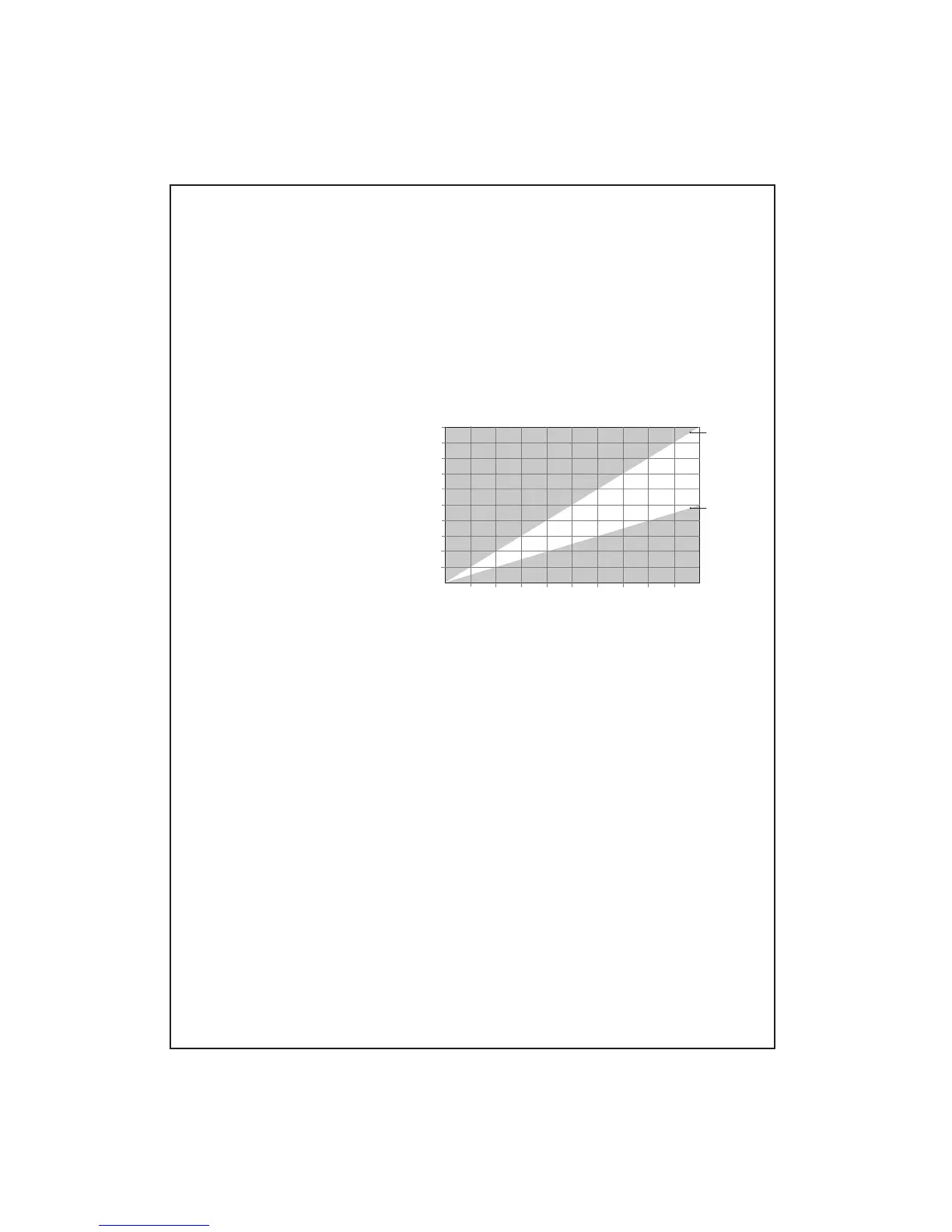
The graph on the right shows the
recommended CSA for different
lengths of loop cable. Simply
work out the length of the loop
required and choose a cable size
that falls into the non-shaded
area of the graph.
50
100
150
200
25
75
125
175
0.511.522.533.544.55
250
0
0
Planning the system
Induction loop system design and installation can be simple provided a few basic facts are
understood. To help avoid poor performance and the need to re-position the amplifier or
loop cable at a later stage, please read pages 6 to 9 before proceeding.
Area of coverage
Maximum square room coverage provided by PDA Pro-Range amplifers is as follows:-
PDA200/2 = 200m
2
(14m x 14m)
; PDA500/2 = 500m
2
(22m x 22m)
; PDA1000/2 = 900m
2
(30m x 30m)
For rectangular (2:1) asect ratio coverage see technical specifications, page 14/15.
Note that the system may not have to cover the whole of a room. For example, churches may only
require coverage in the pews. Seek advice from the relevant authorities before installation begins.
Loop cable position
The field strength in the plane of the loop (the height at which the cable is positioned)
varies greatly so it is best to install the loop above or below the listener at floor or ceiling
height (2.5m max.) - the loop field will not be as strong but it will be much more even and give
better results for the user(s).
Note that listening height (with the hearing aid user sitting or
standing) is normally 0.9 to 1.8m from the floor.
With floor loops, avoid running the loop up and over door openings as the signal strength in
the doorway will be excessively strong and may cause discomfort to the users.
Large amounts of metal can affect the strength of the loop field so avoid running loops along
girders or under floor mesh. If unavoidable, the amplifier’s metal compensation control can help
combat the frequency response problems associated with such installations, but overall current
capability may be reduced, see page 13 for details.
Trial loops
Always run a trial loop and evaluate performance by listening to the signal with a hearing aid or
a dedicated loop test receiver. For compliance with BS7594, we recommend you also test the
system using a pink noise generator and magnetic field strength meter, as described on page 13.
Overspill and ‘cross-talk’
The signal generated by the loop will radiate outside as well as inside the loop. If there are
other loop systems in close proximity, overspill such as this may lead to ‘cross-talk’ (signals
from different loops merging into one). If this is likely to be an issue, special designs of loop
can be implemented to help reduce the overspill field - contact your supplier for details.
For example, to cover a room 30m x 20m
(600m
2
) the loop cable would need to be 100m long (2 sides @ 30m and 2 sides @ 20m). The
recommended cable CSA for a loop this length is between 2mm
2
and 4mm
2
. Therefore, a
PDA1000/2 (which can cover areas up to 900m
2
) using 2.5mm
2
cable would be sufficient.
0.5 Ohm
1 Ohm
RISK OF DISTORTION OR
REDUCED AREA OF COVERAGE
RISK OF OVERHEATING
OKAY
Cable CSA (mm
2
)
Cable Length (in metres)