PDA Pro-Range Instructions • Approved Doc. No. DCP0003168 Rev 1 • Page 5
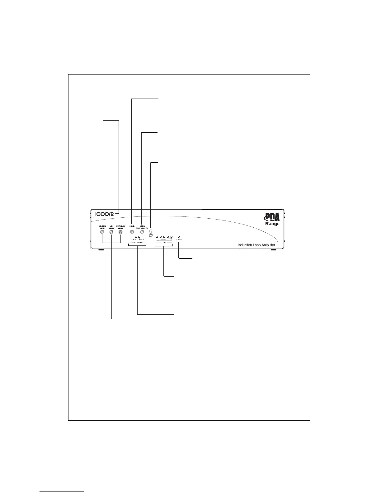
COMPRESSION INDICATORS
Give a visual indication of the amplifier’s compressor activity.
Installers should refer to these indicators when using the
amplifier’s input signal level controls.
For best results, we recommend you set the inputs so that
the LOW compression indicator is lit most of the time and
the HIGH compressor indicator illuminates only with peaks in
the input signal.
LOOP STRENGTH (DRIVE) METER
Gives a visual indication of the current being driven into the
induction loop. In normal circumstances, the far right red LED
should only illuminate with peaks in the input signal.
Installers should refer to these indicators when using the
amplifier’s loop drive control.
LOOP DRIVE CONTROL
Used to adjust the strength of the magnetic field generated by the induction
loop. Turn clockwise to increase the amount of electrical current that is
being driven into the induction loop or anti-clockwise to decrease it.
Always refer to the amplifier’s loop strength meter when adjusting this control.
POWER ON INDICATOR
Illuminates red when the amplifier is powered up.
METAL COMPENSATION CONTROL
Used to help combat the frequency response problems associated with appli-
cations where there is excessive metal ‘absorbing’ the magnetic field. See
page 13 for further details.
MODEL
NUMBER
Indicates the
model number
of the amplifier.
Variants include
the PDA200/2
(for areas up to
200m
2
), the
PDA500/2 (for
areas up to
500m
2
) and the
PDA1000/2 (for
areas up to
900m
2
).
3.5mm LOOP OUTPUT MONITORING SOCKET
Allows the loop current/audio signal that is present in the induction loop to
be monitored using a pair of 32 Ohm headphones. Note that the sound you
hear will be a true representation of the signal running through the loop
and NOT a representation of what hearing aid users will hear after factors
such as metal absorption and their position in the room are taken into
account. You MUST still assess the loop signal in the covered area as
described in connecting and testing the system, pages 10-13.
INPUT SIGNAL LEVEL CONTROLS
Can be used to adjust the sensitivity of
the three input signals (MIC., MIC./LINE
and OUTREACH).
Turn clockwise to increase sensitivity or
anti-clockwise to decrease sensitivity.
For optimum performance, always refer
to the amplifier’s COMPRESSION
indicators when adjusting these controls
(see right).
Depending on the number of inputs
connected to the amplifier, these
controls can also operate as a simple
mixer with any changes having a
cumulative affect on the output signal.