PDA Pro-Range Instructions • Approved Doc. No. DCP0003168 Rev 1 • Page 11
SW1
1
2
3
4
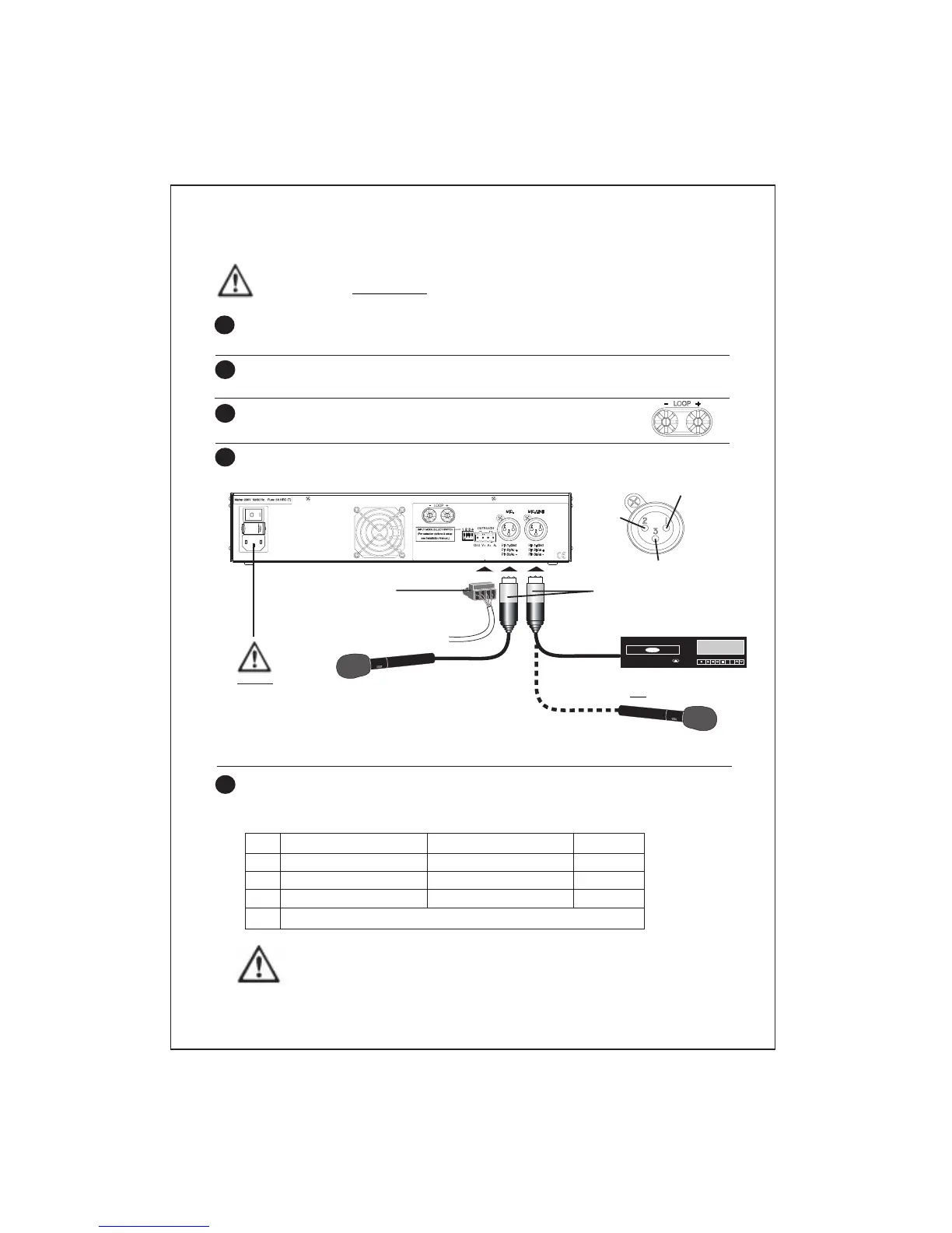
Connecting and testing the system
Install the loop - see Planning the System, pages 6 to 9, for example layouts and
positioning advice.
Before connecting the loop to the amplifier, use a multimeter to check the loop is not
shorted to ground at any point. It WILL almost certainly damage the amplifier if it is.
Connect the loop to the amplifier’s heavy duty binding posts
using bare wire ends, 4mm plugs or spade terminals as appropriate.
Connect an input signal source (microphone, line, outreach or any combination of
these) to the amplifier as shown below.
1
2
3
4
IMPORTANT : DO NOT POWER UP THE SYSTEM UNTIL STEP 7 (OVERLEAF).
THE AMPLIFIER SHOULD NOT BE OPERATED WITHOUT A LOOP CONNECTED TO IT.
3 pin XLR connectors
Ensure pin arrangements
match those shown above.
Microphone
4-way Outreach connector
For more detailed information on
Outreach plate wiring see page 7.
Set the Input Mode Select Switches to their correct positions with reference to the
table below. Note that the position of the switches will depend upon the type of
inputs that are connected to the amplifier.
5
Line level input, i.e. CD player
Gnd
Au+
Au–
Microphone
DO NOT
connect the
Mains lead
until point 7
overleaf
OR
OFF (up)
11V phantom power off
11V phantom power off
Line operation
ON (down)
11V phantom power on
11V phantom power on
Mic. operation
------------------------- Switch 4 has no function -------------------------
Note that if Switch 3 is in the OFF (up) position (MIC./LINE input set for line operation),
Switch 2 MUST also be in the OFF (up) position (11V phantom power off). Failure to do
so could result in damage to any line level equipment you connect to the amplifier.
Input
MIC.
MIC./LINE
MIC./LINE