PDA Pro-Range Instructions • Approved Doc. No. DCP0003168 Rev 1 • Page 4
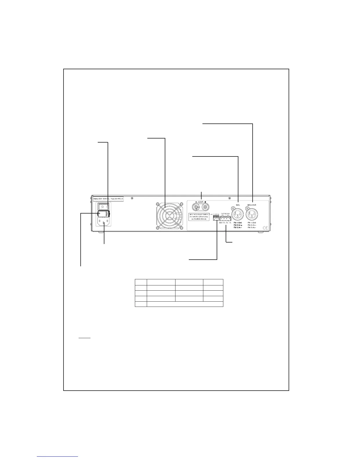
INPUT MODE SELECT SWITCH
Allows the MIC./LINE input to be configured for
Mic or Line operation and for optional 11V phantom
power to be switched to the inputs.
SW1
1
2
3
4
Familiarisation with your Pro-Range induction loop amplifier
MIC. INPUT
Accepts standard three-pin male XLR
type connectors. Optional 11V
phantom power is available via input
mode select switch 1.
MIC./LINE INPUT
Accepts standard three-pin male XLR type
connectors. Can be configured for Mic. or Line
operation via input mode select switch 3.
Optional 11V phantom power is available via
input mode select switch 2.
OUTREACH INPUT
Allows the connection
of up to ten additional
microphone or line
level inputs via a range
of specially designed
single gang connector
plates (see page 7 for
further details).
POWER
SWITCH
INDUCTION LOOP
CONNECTORS
230V AC
POWER LEAD
CONNECTOR
Below and overleaf is an overview of the indicators, controls and connectors available on
your PDA Pro-Range induction loop amplifier. Detailed connection diagrams, system
planning and system set-up information can be found later in this manual.
COOLING FAN
Provided on PDA1000/2
& PDA500/2 models only
Operates automatically
when the temperature of
the amplifier’s internal
heat sink reaches 56
o
C.
It is perfectly normal for
this fan to switch on and
off during everyday use.
MAINS FUSE
All models feature an IEC
(EN60127 part 2) compliant
mains fuse, as detailed below:
PDA200/2
2A T 20mm anti-surge
ceramic HRC type.
PDA500/2
3.15A T 20mm anti-surge
ceramic HRC type.
PDA1000/2
5A T 20mm anti-surge
ceramic HRC type.
Do not use any other type or
size of fuse other than those
shown above.
OFF (up)
11V phantom off
11V phantom off
Line operation
ON (down)
11V phantom on
11V phantom on
Mic. operation
Input
MIC.
MIC./LINE
MIC./LINE
----------------- Swiitch 4 has no function -----------------
Note that if Switch 3 is in the OFF (up) position (MIC./LINE
input set for line operation), Switch 2 MUST also be in the
OFF (up) position (11V phantom power off). Failure to do
so could result in damage to any equipment you
connect to the amplifier.