Wiring Guidelines—Oponal for TruSwim Propulsion System (60 Hz) North America
29
Your new TruSwim Swim Spa will arrive from the factory wired to operate with a single 120/240 volt 50 Amp Ground Fault
Circuit Interrupter Type A circuit breaker (not included from PDC) supplied from the homeowner’s power source.
The system, when wired this way, is designed to turn off the high speed of the jet pump and heater while the TruSwim
propulsion system is operang. Since water cools slowly, this is adequate for most installaons.
If you choose, the swim spa can be wired with an addional 240 volt 30 amp Ground Fault Circuit Interrupter (not supplied)
power source from the home owners electrical power. The addion of the 30 amp circuit will allow the high speed of the jet
pump and the heater to operate simultaneously with the TruSwim propulsion system aer a programming change is made to
the operang system of the swim spa. This programming change is not supplied with this manual due to the possibility of
other features being changed accidentally. Your swim spa retailer should have the informaon needed to make the necessary
programming change. In the event he does not or no retailer is available contact our customer service for assistance.
StepsforAddingAddionalPowerSupply
1. Make sure all electrical power is turned off before performing service.
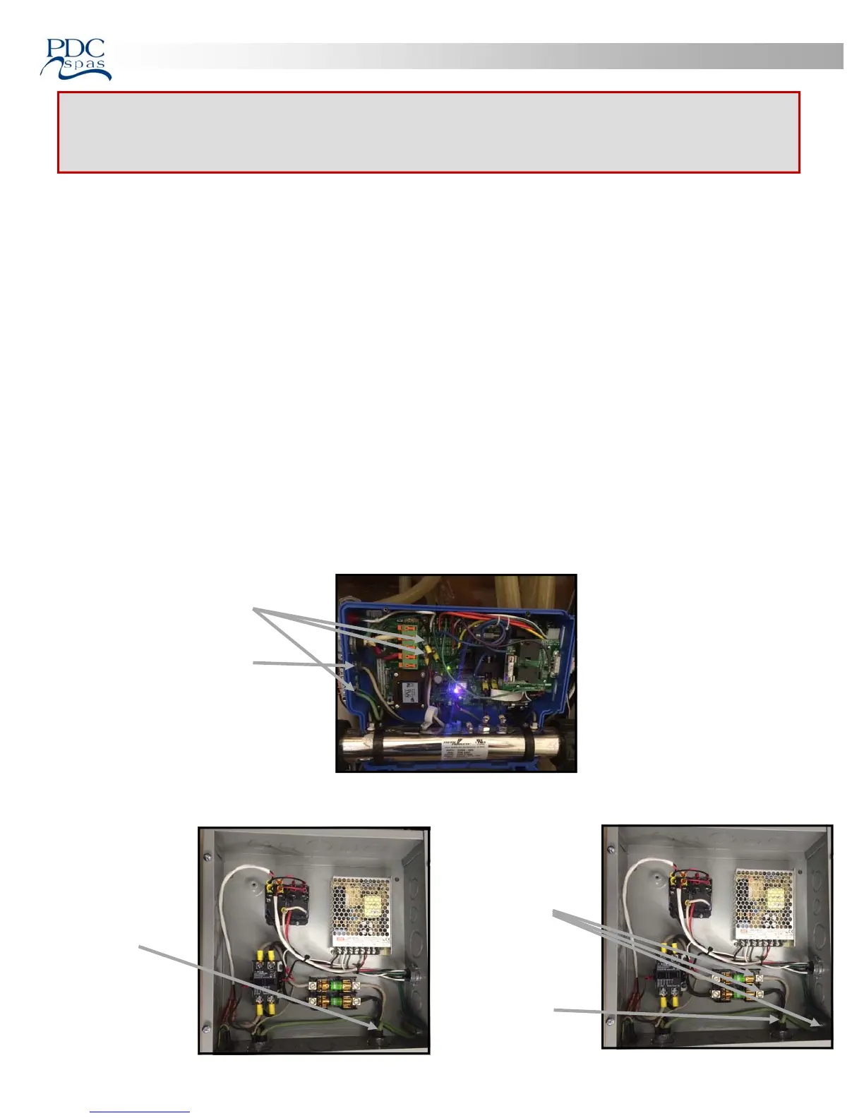
2. Disconnect and remove wire #1 from both the relay center and spa control center. See figure #1 and figure #2.
3. Install the 30 amp 240 volt ground fault circuit protected L1 and L2 legs into the fuse block and the ground wire in the
ground strip where the wire was removed from the relay control center as shown in figure #3.
4. Place a cap into the hole le behind from the removal of wire #1 in the spa control center.
5. FOLLOWALLOTHERSTARTUPPROCEDURESWITHINTHISMANUAL.
FORQUALIFIEDELECTRICIANREFERENCEONLY!
Allinstallaonsandconneconsaretobeperformedbyaqualified,licensedelectricianonly
andinaccordancewiththeNaonalelectriccodeandallapplicablelocalregulaons.
Ensurepoweristurnedoffpriortomakinganyelectricalconnecons.
FIGURE#1
Remove wire #1
Remove Strain
Relief and cap
remaining hole
Remove wire #1
FIGURE#2
FIGURE#3
L1, L2, &
ground wire
connecon
30 amp 240 volt
ground fault
circuit
protected feed
 Loading...