PCAN-USB – User Manual
12
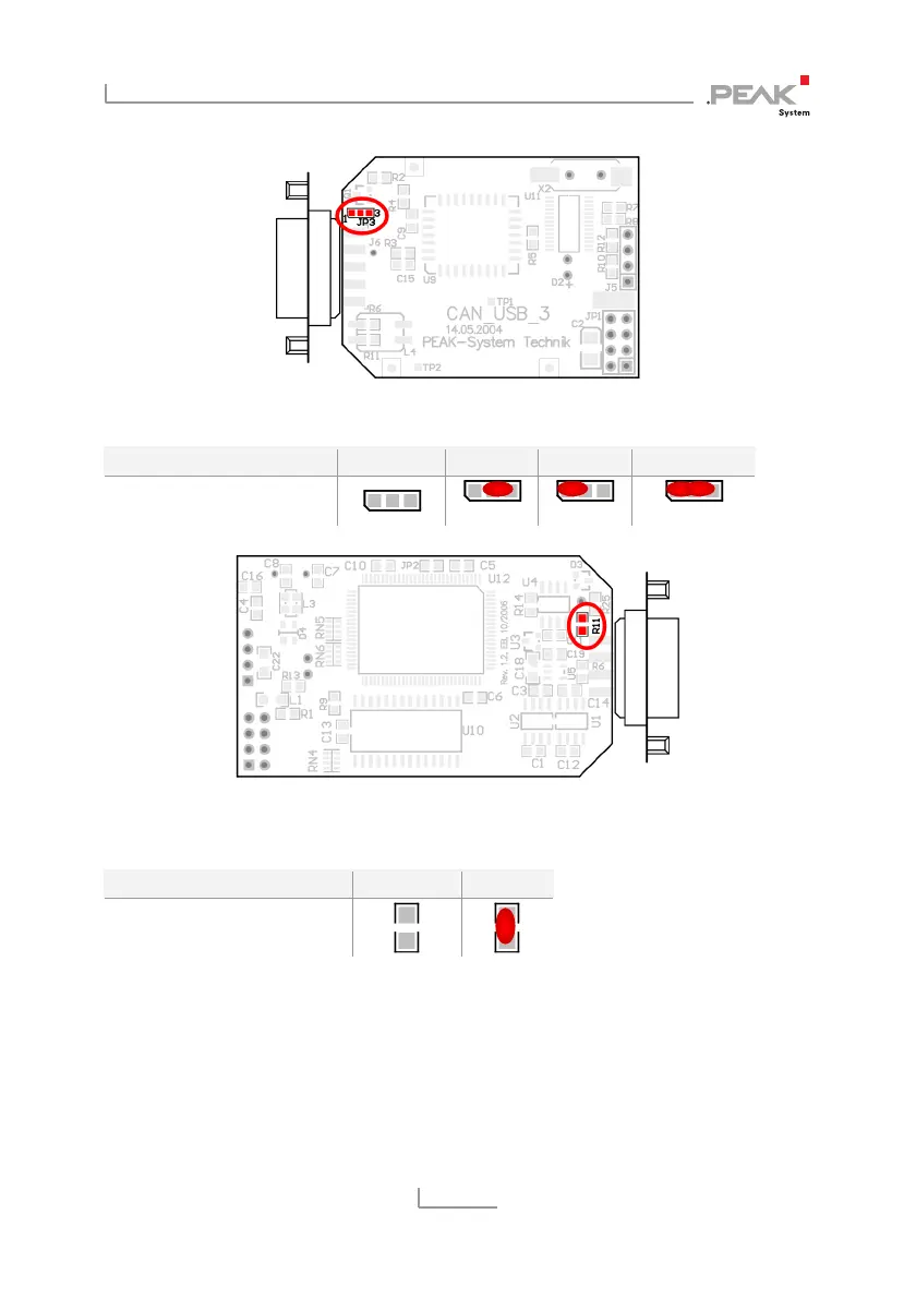
Figure 2: PCAN-USB board (IPEH-002021), solder field JP3
5-Volt supply →
None Pin 1 Pin 9 Pin 1 + Pin 9
PCAN-USB, solder field
JP3
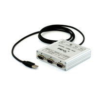
Figure 3: Bottom side of the PCAN-USB opto-decoupled board (IPEH-002022),
solder field R11
5-Volt supply →
None Pin 1
PCAN-USB opto-decoupled,
solder field R11
For reassembly place the board overhead onto the top part of the
casing. Ensure that the cable is lying with the strain relief in the cut-
out of the casing, and that the LED is placed in the corresponding
hole. Push the bottom part of the casing onto the top part (the
latches click in).