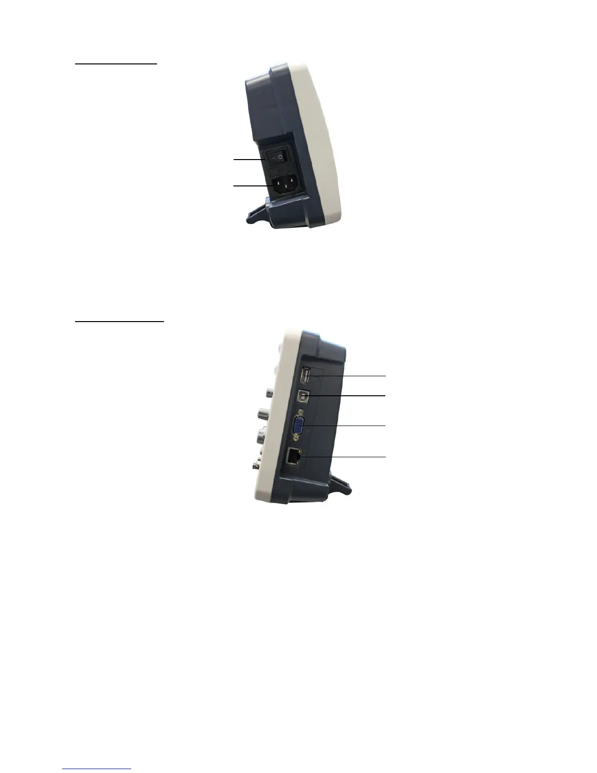
3.3. Left side panel
Fig. 2 Left side panel
1. Power switch:“―” represents power ON; “○” represents power OFF.
2. AC power input jack
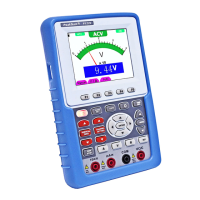
3.4. Right side panel
Fig. 3 Right side panel
1. USB Host port: It is used to transfer data when external USB equipment connects to the oscilloscope
regarded as “Host equipment”. For example: upgrading software by USB flash disk
needs to use this port.
2. USB Device port: It is used to transfer data when external USB equipment connects to the oscilloscope
regarded as “Device equipment”. For example: to use this port when connect PC to the
oscilloscope by USB.
3. VGA port: To connect the oscilloscope with a monitor or a projector as VGA output.
4. LAN: To integrate this oscilloscope into a network.
-95-
1.
2.
1.
2.
3.
4.