Do you have a question about the PeakTech 2755 and is the answer not in the manual?
Explanation of safety symbols used in the manual, including risk of electric shock and over-voltage warnings.
Lists the European standards (EN) that the instrument has been tested against for safety and EMC.
Details the ranges, resolution, and accuracy for Loop Resistance measurements (L-PE Hi-Amp and No Trip).
Details the ranges, resolution, and accuracy for Line Resistance measurements (L-N).
Specifies RCD ratings (In) and test currents for RCD testing according to EN 61557-6.
Specifies accuracy for different test currents (x1/2, x1, x2, x5) and test parameters like waveform and polarity.
Details the measurement range, resolution, and accuracy for Voltage and Frequency.
Details ranges, resolution, accuracy, max open circuit voltage, and overload protection for Low Ohm measurements.
Details ranges, resolution, and accuracy for Earth Resistance measurements.
Provides overall technical specifications for the instrument including power, battery, CAT rating, protection, display, and operating conditions.
Defines key terms and functions used in the manual, such as RCD AUTO, RCD TIME, UF, and UL.
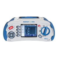
Detailed description of each function key (F1-F4) and their roles in operating the tester.
Identifies and describes the various input and output terminals on the tester.
Details the types and specifications of fuses and batteries used in the instrument.
Explains the meaning of various icons, symbols, and display elements shown on the instrument's screen.
Details display elements and values related to RCD testing functions.
Details display elements and values related to Loop and PFC testing functions.
Details display elements and values related to Voltage/Phase testing.
Details display elements for Continuity and Terminal Voltage settings.
Explains display values for Trip Current, RCD Type, Lock, and Zero settings.
Details display values for RCD type, lock status, phase twist, zero function, and reference values.
Explains battery status indicators, beeper, hold, and datalogger functions.
Explains symbols for Bluetooth connection status and overheat warnings.
Describes the display indication for time-delayed RCD measurements.
Indicates when a measurement is currently being performed by the tester.
Explains the primary and secondary display values and their measurement units (e.g., Ω, mA).
Explains the display of fault voltage (UF) and the preset fault voltage limit (UL).
Shows how terminal indicator symbols indicate correct or reversed polarity connections.
Explains the display of values for N-PE, L-N, and L-PE connections.
Explains the display of Prospective Fault Current (PFC) and Prospective Short-Circuit Current (PSC).
Details the high voltage warning symbol and associated safety precautions.
Explains important symbols and messages that appear on the display during measurements.
Explains icons and messages specific to the Voltage measurement function, including connectivity and battery status.
Explains icons and messages specific to Loop and PFC measurement functions.
Explains icons and messages specific to the RCD measurement functions.
Explains icons and messages for Low Ohm and Continuity testing, including zero function and battery status.
Explains icons and messages for Earth Resistance (RE) testing, including zero function and battery status.
Explains icons and messages for Insulation testing, including high voltage warnings and battery status.
Procedure for using the zero adapter to calibrate lead resistance for Loop/PFC measurements.
How to select the UL Voltage setting (25V or 50V) using the F4 button.
Table showing possible setup ratios for RCD trip currents (10mA to 1A).
Details maximal measurement trip times for General and Selective RCDs based on BS 61008 and 61009.
Details on using the F3 button for selective (time-delayed) RCD testing and AC/DC current types.
Explains how to use the F4 button to select phase twist (0°/180°) for RCD testing.
Describes how to navigate and operate the menus for Voltage/Phase functions.
Details the function menus for Isolation Measurement, including Beeper, Lock, and Terminal Voltage settings.
Describes how to navigate and operate the menus for Earth Resistance (RE) functions, including zero function.
Describes how to navigate and operate the menus for Low Ohm functions, including zero function.
Configuration options for the tester, including language, date/time, TV output, memory, and auto power settings.
Instructions for selecting the display language for the instrument.
Procedure for setting the current date and time on the tester.
Options for configuring the TV output format (Off, PAL, NTSC).
Information on working space and formatting the internal memory or SD card.
Configuration for the auto screen-off timer to conserve battery power.
Configuration for the auto power-off timer to prevent battery discharge.
Procedure for resetting the tester to factory default settings.
Information on updating the instrument's firmware via an SD card.
Settings related to running the tester, including Bluetooth and Data Record options.
Instructions for enabling and using Bluetooth for data transfer.
Details on recording single readings to a text file and transferring them to a PC.
Instructions for using the datalogger to record measured values over time.
Explains options for file deletion, Bluetooth transfer, and drawing view settings within the Data Record menu.
Instructions for installing and using the PeakTech Safety Tester PC software for data transfer.
| Diode | Yes |
|---|---|
| Battery Test | 1.5V / 9V |
| Power Supply | 9V battery |
| Type | Digital Multimeter |
| Continuity | Yes |
| Frequency Range | 10Hz to 10MHz |
| Temperature Range | -20°C ~ 1000°C |