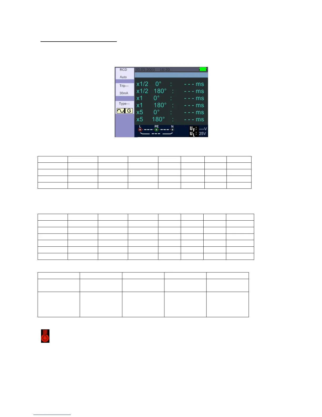
5.2.5 Using the RCD Function
You can select UL Voltage by pressing and hold F3 button for more than two seconds (25V or 50V).
Uf value appears is the contact voltage on the screen.
RCD – Standby screen
Function Button Description
G …………………….General (non-delayed) RCDs
S …………………….Selective (time-delayed) RCDs
Possible setup ratios depending on the RCD Trip Current
Maximal measurement Trip Time of the RCD (Complying to BS 61008 and 61009)
General (non-
delayed) RCD
Selective
(time-delayed)
RCDs
I∆N………………………... Trip-Out Current
t∆…………………………. Trip-Out Time
: Indicates that the thermal protection device prevented the tester from overheating and you
therefore cannot make a measurement. Please let the instrument cool down.
-75-