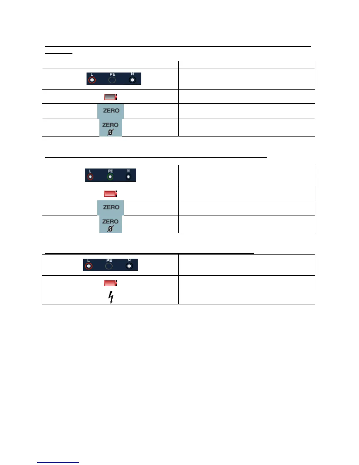
5.1.4. Displayed icons (symbols) and messages when using the LOW OHM and CONTINUITY
functions
Indicates correct input terminal connectivity. The
user should connect the test leads to the
appropriate terminals indicated by color coding.
Low Battery (The icon will be flashing along with
the beep sound)
The resistance of the test leads are included in
the test measurement
The resistance of the test leads are not included
in the test measurement
5.1.5. Displayed icons (symbols) and messages when using the RE functions
Indicates correct input terminal connectivity. The
user should connect the test leads to the
appropriate terminals indicated by color coding.
Low Battery (The icon will be flashing along with
the beep sound)
The resistance of the test leads are included in
the test measurement
The resistance of the test leads are not included
in the test measurement
5.1.6. Displayed icons (symbols) and messages in INSULATION function
Indicates correct input terminal connectivity. The
user should connect the test leads to the
appropriate terminals indicated by color coding.
Low Battery (The icon will be flashing along with
the beep sound).
Indicates high voltage (125V, 250V,500V or
1000V) at probe terminals, Use caution