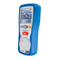
5.3.2. To measure insulation resistance
1. Turn the rotary switch to the INSULATION position.
2. Use the L and N (red and black) terminals for this test.
3. Use the F1 to select the test voltage. Most insulation testing is performed at 500 V, but
observe local test requirements.
4. Press and hold TEST button until the reading settles and the tester beeps.
Note
Testing is inhibited if voltage is detected in the line.
The primary (upper) display shows the insulation resistance.
The secondary (lower) display shows the actual test voltage.
Note
For normal insulation with high resistance, the actual test voltage (UN) should always be equal to or
higher than the programmed voltage. If insulation resistance is bad, the test voltage is automatically
reduced to limit the test current to safe ranges.
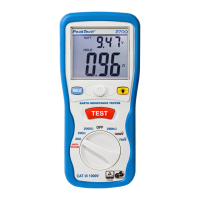
5.4. Using the RE Function
The earth resistance test is a 3-wire test based on the fall-of-potential method. The two test stakes
(H for test AC current, S for potential measurement) and the earth electrode (RE) are used. Connect
them as shown in the figure below.
Schematic setup for measuring earth resistance (RE)
-84-