29
5.4. Resistance
WARNING !
Never apply an external voltage to the sockets damage to the
meters may result.
1. Set the Function/Range switch to the desired range
2. Insert the red test lead into
.
))) socket and the black
test lead into COM-socket.
3. Read the resistance directly from the display
Note
* The resistance in the test leads can diminish accuracy on the
lowest (200 ) range. The error is usually 0.1 to 0.2 for a
standard pair of test leads. To determine the error, short the
test leads together and then use the (REL) Relative mode to
automatically subtract the lead resistance from resistance
measurements.
* For high resistance measurement (>1M), it is normal taking
several seconds to obtain a stable reading.
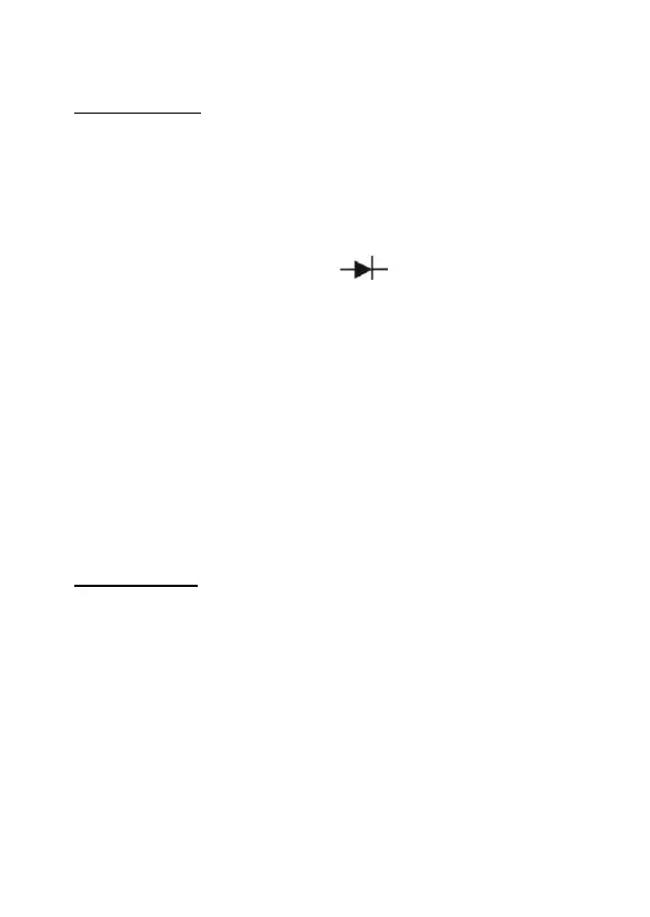
5.5. Diode Test
WARNING !
To avoid damages to the Meter or to the devices under test,
disconnect circuit power and discharge all the high-voltage,
capacitors before measuring diodes and continuity.
Testing Diodes
Use the diode test to check diodes, transistors, and other
semiconductor devices. The diode test sends a current through
the semiconductor junction. And then measures the voltage drop
across the junction. A good silicon junction drops between 0,5 V
and 0,8 V.
 Loading...