REAR
PANEL
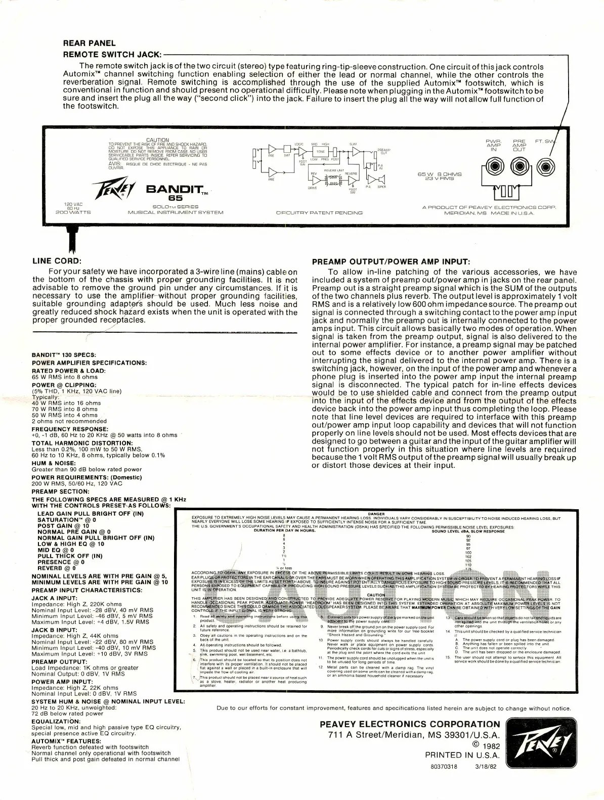
REMOTE
SWITCH
JACK;
The
remote
switch
jack
isof
the
two
circuit
(stereo)
type
featuring
ring-tip-sleeve
construction.
Onecircuit
of
this
jack
controls
Automix'"
channel
switching
function
enabling
selection
of
either
the
lead
or
normal
channel,
while
the
other
controls
the
reverberation
signal.
Remote
switching
is
accomplished
through
the
use
of
the
supplied
Automix™
footswitch,
which
is
conventional
in
function
and
should
present
no
operational
difficulty.
Please
note
when
plugging
in
the
Automix™
footswitch
to
be
sure
and
insert
the
plug
all
the
way
("second
click")
into
the
jack.
Failure
to
insert
the
plug
all
the
way
will
not
allow
full
function
of
the
footswitch.
190
VAC
60
Hz
SOD
WATTS
CAUTION
TO
PREVENT
THE
RISK
OF
FIRE
AND
SHOCK
HAZARD.
00
NOT
EXPOSE
THIS
APPLIANCE
TO
RAIN
OR
MOISTURE
DO
NOT
REMOVE
FROM
CASE.
NO
USER
SERVICEABLE
PARTS
INSIDE.
REFER
SERVICING
TO
QUALIFIED
SERVICE
PERSONNEL.
AVIS:
RISQUE
DE
CHOC
ELECTRIQUE
-
NE
PAS
OUVRIR.
7^/
BANDIT^
65
SOLOtm
series
MUSICAL
INSTRUMENT
SYSTEM
PWR,
PRE
FT.
SV
AMP AMP
IN
OUT
y
CIPCUITRY
PATENT
PENDING
A
PRODUCT
DF
PEAVEY
ELECTRONICS
CDHP.
MERIDIAN,
MS
MADE
IN
U.S.A.
LINE
CORD:
For
your
safety
we
have
incorporated
a3-wireline
(mains)
cable
on
the
bottom
of
the
chassis
with
proper
grounding
facilities.
It
is
not
advisable
to
remove
the
ground
pin
under
any
circumstances.
If
it
is
necessary
to
use
the
amplifier
without
proper
grounding
facilities,
suitable
grounding
adapter's
should
be
used.
Much
less
noise
and
greatly
reduced
shock
hazard
exists
when
the
unit
is
operated
with
the
proper
grounded
receptacles.
BANDIT'"
130
SPECS;
POWER
AMPLIFIER
SPECIFICATIONS:
RATED
POWER
&
LOAD:
65
W
RMS
into
8
ohms
POWER
@
CUPPING:
(5%
THD,
1
KHz,
120
VAC
line)
Typically;
40
W
RMS
into
16
ohms
70
W
RMS
into
8
ohms
50
W
RMS
into
4
ohms
2
ohms
not
recommended
FREQUENCY
RESPONSE:
+0,
-1
dB,
60
Hz
to
20
KHz
@
50
watts
into
8
ohms
TOTAL
HARMONIC
DISTORTION:
Less
than
0.2%,
100
mW
to
50
W
RMS,
60
Hz
to
10
KHz,
8
ohms,
typically
below
0.1%
HUM
&
NOISE:
Greater
than
90
dB
below
rated
power
POWER
REQUIREMENTS:
(Domestic)
200
W
RMS,
50/60
Hz,
120
VAC
PREAMP
SECTION:
PREAMP
OUTPUT/POWER
AMP
INPUT:
To
allow
in-line
patching
of
the
various
accessories,
we
have
Included
a
system
of
preamp
out/power
amp
in
jacks
on
the
rear
panel.
Preamp
out
is
a
straight
preamp
signal
which
is
the
SUM
of
the
outputs
of
the
two
channels
plus
reverb.
The
output
level
is
approximately
1
volt
RMS
and
is
a
relatively
low
600
ohm
impedance
source.
The
preamp
out
signal
is
connected
through
a
switching
contact
to
the
poweramp
input
jack
and
normally
the
preamp
out
is
internally
connected
to
the
power
amps
input.
This
circuit
allows
basically
two
modes
of
operation.
tWhen
signal
is
taken
from
the
preamp
output,
signal
is
also
delivered
to
the
internal
power
amplifier.
For
instance,
a
preamp
signal
may
be
patched
out
to
some
effects
device
or
to
another
power
amplifier
without
interrupting
the
signal
delivered
to
the
internal
power
amp.
There
is
a
switching
jack,
however,
on
the
input
of
the
power
amp
and
whenever
a
phone
plug
is
inserted
into
the
power
amp
input
the
internal
preamp
signal
is
disconnected.
The
typical
patch
for
in-line
effects
devices
would
be
to
use
shielded
cable
and
connect
from
the
preamp
output
into
the
input
of
the
effects
device
and
from
the
output
of
the
effects
device
back
into
the
power
amp
input
thus
completing
the
loop.
Please
note
that
line
level
devices
are
required
to
interface
with
this
preamp
out/power
amp
input
loop
capability
and
devices
that
will
not
function
properly
on
line
levels
should
not
be
used.
Most
effects
devices
that
are
designed
to
go
between
a
guitar
andtheinputoftheguitaramplifierwill
not
function
properly
in
this
situation
where
line
levels
are
required
because
the
1
volt
RMS
output
of
the
preamp
signal
will
usually
break
up
or
distort
those
devices
at
their
Input.
THE
FOLLOWING
SPECS
ARE
MEASURED
@
1
KHz
WITH
THE
CONTROLS
PRESET
AS
FOLLOWS:
LEAD
GAIN
PULL
BRIGHT
OFF
(IN)
SATURATION
"
@
0
POST
GAIN
@
10
NORMAL
PRE
GAIN
@
0
NORMAL
GAIN
PULL
BRIGHT
OFF
(IN)
LOW
8,
HIGH
EO
@
10
MID
EG
@
0
PULL
THICK
OFF
(IN)
PRESENCE
@
0
REVERB
@
0
NOMINAL
LEVELS
ARE
WITH
PRE
GAIN
@
5,
MINIMUM
LEVELS
ARE
WITH
PRE
GAIN
@
10
PREAMP
INPUT
CHARACTERISTICS:
JACK
A
INPUT:
Impedance:
High
Z.
220K
ohms
Nominal
Input
Level:
-28
dBV,
40
mV
RMS
Minimum
Input
Level:
-46
dBV,
5
mV
RMS
Maximum
Input
Level:
■'■4
dBV,
1.5V
RMS
JACK
B
INPUT:
Impedance:
High
Z,
44K
ohms
Nominal
Input
Level;
-22
dBV,
80
mV
RMS
Minimum
Input
Level:
-40
dBV,
10
mV
RMS
Maximum
Input
Level:
+10
dBV,
3V
RMS
PREAMP
OUTPUT:
Load
Impedance:
IK
ohms
or
greater
Nominal
Output:
0
dBV,
IV
RMS
POWER
AMP
INPUT:
Impedance:
High
Z,
22K
ohms
Nominal
Input
Level:
0
dBV,
IV
RMS
SYSTEM
HUM
&
NOISE
@
NOMINAL
INPUT
LEVEL:
20
Hz
to
20
KHz,
unweighted:
72
dB
below
rated
power
EQUALIZATION:
Special
low.
mid
and
high
passive
type
EQ
circuitry,
special
presence
active
EQ
circuitry,
AUTOMIX"
FEATURES:
Reverb
function
defeated
with
footswitch
Normal
channel
only
operational
with
footswitch
Pull
thick
and
post
gain
defeated
in
normal
channel
DANGER
EXPOSUFIE
TO
EXTREMELY
HIGH
NOISE
LEVELS
MAY
CAUSE
A
PERMANENT
HEARING
LOSS.
INDIVIDUALS
VARY
CONSIDERABLY
IN
SUSCEPTIBILITY
TO
NOISE
INDUCED
HEARING
LOSS,
BUT
NEARLY
EVERYONE
WILL
LOSE
SOME
HEARING
IF
EXPOSED
TO
SUFFICIENTLY
INTENSE
NOISE
FOR
A
SUFFICIENT
TIME.
THE
U.S.
GOVERNMENT'S
OCCUPATIONAL
SAFETY
AND
HEALTH
ADMINISTRATION
(OSHA)
HAS
SPECIFIED
THE
FOLLOWING
PERMISSIBLE
NOISE
LEVEL
EXPOSURES-
DURATION
PER
DAY
IN
HOURS.
SOUND
LEVEL
dSA,
SLOW
RESPONSE
8
90
6
92
ACCORDING..T:0;;e6ft«j:««Y.
EXI
EAR
PLUG6l0fil:efi!Gt^e£:®aftfi;;fN
THE
EXPOSU8gtS:f«-EXCES5WW£
LIMITS
PERSON3:-eX0CSED
TO
EaaVRlteNT
"
'
UNIT
IS;a^:0?eFlATION
:
EA
THIS
Aj#tfSiER
HAS
BEEN
DESI
HANDLi^StCCASIONAL
PEAK
PO'
RECOMttetJCSDSINCE
THfSSiGULD
Q
CONTROjiSfJK^T-HE
INPU.TSStQf^fAL
If
1
lU:ud
msuuciion!;
biilur^
produci
safely
and
operaling
instructions
should
be
n
R
C!««SCft::-dR
OVER
I
■
M
LAiLtMi
'
i
ITS
ASlSgiJSiMtH
ABOVE.
rSliSiSURE
i
.F
IISSIBLE
LtofTS
W4.60M6
HEilSfttSa
LOSS.
1ST
8EW<)St<:.WHEI)it^&BEfiA'^t»S:TWfS-«i»PLtF(C«TiONSYSTSM!4Nl£^OEBI:T©:PRBVeNTAPEBMA«6hJTHeARi(i^tbsSlF
■i
AGAINgj;SS3TENriA"i:LY-ti&S(S£fidUS
EXPOStifiSTO
HIGK;g<3i{fi»
PRESSUHeifcEVELS.
l1?:t6!a6CdW.MENDE®fE«*T
ALL
ND
PRESSkH^
levels
SUCH:AS:THISAMPLIFtCj«iiS:JON
SYSJi^lSE
PROTECTEtSeWlHEARIfWaflRpirtCTORSriilSStttf
THIS
futuri
Obey
a
■k
of
tl-
1
the
operating
4.
All
operaling
instructions
should
be
Ic
5.
T^hls
product
should
not
be
used
near
^ink,
swimming
pool,
wet
basement,
e
;6,
/This
product
should
be
located
so
the-
interlere
with
its
proper
ventilation,
it
:
flat
against
a
wail
or
placed
in
a
built-
Impede
the
llow
ot
cooling
air
,
7.^
jThis
product
should
not
be
placed
rear
power
supply
c#;aj9::^pe
marked
ortJhe^tfnit
■
power
supply
cSSiHiiV-
Si-L-iliB?
9.
Never
break
off
the
ground
pjn
on
the
power
supply
cord
For
more
imormaiion
on
grounding
write
tor
our
free-booklet
"Shock
Hazard
and
Grounding."
10
Power
supply
cords
should
always
be
handled
carefully
Never
walk
or
place
equipment
on
power
supply
cords
Periodically
check
cords
for
cutsorsigns
distress,
especially
at
the
plug
and
the
point
where
the
cord
exits
the
unit
11.
The
power
supply
cord
should
be
unplugged
when
the
unil
is
to
be
unused
for
long
periods
of
time.
12
Metal
parts
can
be
cleaned
with
a
damp
rag
The
vinyl
covering
used
on
some
units
can
be
cleaned
with
a
damp
rag.
d
cleaner
it
necessary
C«e«r6t>fcJ
fj((-ti»'5.'n
•-(
the
uni
diner
openings
by
a
qualitied
service
lechmcia.
or
plug
has
been
damaged.
The
power
supply
cord
or
plug
has
b
Anything
has
lalien
or
been
spilled
In
The
unit
does
not
operate
correctly
The
unit
has
been
dropped
or
the
enclosure
damaged
e
user
should
not
attempt
to
service
this
equipment
All
-vice
work
should
bedoneby
a
qualified
service
technician
Due
to
our
efforts
for
constant
improvement,
features
amd
specitications
iisteid
herein
are
subject
to
change
without
notice.
PEAVEY
ELECTRONICS
CORPORATION
711
A
Street/Meridian,
MS
39301/U.S.A.
©
1982
PRINTED
IN
U.S.A.
80370318
3/18/82

 Loading...