Do you have a question about the Peavey BANDIT 75 and is the answer not in the manual?
Primary input for most electric guitars, offering higher gain than the Low Gain input.
Input for instruments with very high outputs to prevent overdriving the High Gain input.
Selects between the lead and normal channels; 'in' selects lead, 'out' selects normal.
Details on rated power, clipping, frequency response, THD, and hum/noise.
Specifications for preamp inputs, equalization, and overall system hum/noise.
Crucial safety information regarding high noise levels and general appliance handling.
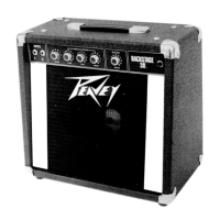
| Brand | Peavey |
|---|---|
| Model | BANDIT 75 |
| Category | Musical Instrument Amplifier |
| Language | English |