9
red binding post associated with Channel A should be considered the positive output for the system and
thus should be connected to the positive input of the associated loudspeaker system.
WWAARRNNIINNGG::
Regardless of what connections are used, the minimum parallel speaker load should always be
limited to 2 Ohms per channel or 4 Ohms “bridge” mode for any application (4 Ohms per channel/8 Ohms
bridge for GPS 3500). Operation at loads of 4 Ohms per channel or 8 Ohms “bridge” mode is more
desirable for sustained operation applications due to the fact that the amplifier will run much cooler at this
loading. Operation above 4 Ohms per channel and even open circuit conditions can always be considered
safe.
DDDDTT CCOOMMPPRREESSSSIIOONN
1111.. DDDDTT DDEEFFEEAATT
This switch is used to defeat the DDT compression used to protect against signal clipping.
OOnnllyy tthhee GGPPSS
990000 aanndd 11550000 mmooddeellss ooffffeerr tthhiiss ffeeaattuurree..
It is recommended to leave the DDT compression enabled at all
times to protect your speakers from damaging square waves. The DDT function is disabled when the switch
is pressed to the “in” position. The DDT LEDs (12) will illuminate when DDT compression is occurring in that
particular channel.
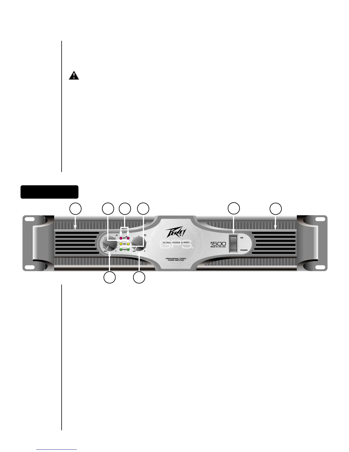
FFRROONNTT PPAANNEELL CCOONNTTRROOLLSS//IINNDDIICCAATTOORRSS
The following section describes the controls and indicators found on the front panel of your GPS Series
amplifier. The Power Switch and LED are explained in a previous section, AC Power.
1122.. DDDDTT LLEEDDss
The DDT LEDs will illuminate when signal compression is occurring in that channel. If you have a GPS 900
or 1500 and you have the DDT compression defeated, these LED will indicate the channel is clipping.
1133.. SSiiggnnaall LLEEDDss
Each channel has a Signal LED, which comes on when the amplifier channel output exceeds 1 Volt.
1144.. IInnppuutt GGaaiinn
Each channel has an Input Gain control used to adjust the gain of the input signal. Maximum power
amplifier input gain (minimum sensitivity) is achieved at the full clockwise setting (30 dB or 40x). This
setting yields maximum mixer/system headroom. A setting of less than full clockwise will yield lower
system noise at the expense of headroom.
1155.. FFaann GGrriillll ((llooccaatteedd oonn ffrroonntt aanndd rreeaarr ppaanneell))
Two continuously variable-speed DC fans supply cool air to the amplifier.
GGPPSS 990000 aanndd 11550000
The fans operate at a quiet, low speed when the unit is turned on. The speed of the fans increase as the
amplifier heatsinks require cooling. (See Operation Notes.)
GGPPSS 22660000,, 33440000 aanndd 33550000
The fans do not operate when the unit is first turned on. The operation and speed of the fans are
temperature dependent and change as the amplifier heatsinks require cooling. (See Operation Notes.)
12
15
2
14
14
15
13 3
FFrroonntt PPaanneell
 Loading...