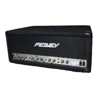
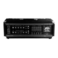
Do you have a question about the Peavey IA 400 and is the answer not in the manual?
Illuminates when the amplifier is overdriven, indicating clipping or reduced signal.
Illuminates when AC power is supplied; turns off if a fault occurs or breaker trips.
Limit current to protect the transformer from overheating and damage due to fault conditions.
Connect to an independent mains circuit capable of supporting at least 15 amps continuously.
Terminal strip for connecting speakers; recommended minimum load is 4 ohms.
Separate barrier strip for each channel, electronically balanced inputs.
Adjust input gain of each channel for optimal signal amplitude and noise.
Mount at the top of equipment stack to prevent overheating sensitive equipment.
Mount in a standard 19" rack for sustained high power operation; ensure adequate cool air supply.
Converts a 2-channel amplifier into a single channel unit with combined power rating.
Wiring diagram for balanced input connections using a 3-terminal barrier strip.
Wiring diagram for unbalanced input connections using a 3-terminal barrier strip.

