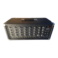
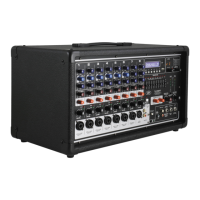
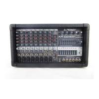
The Peavey PA 700S is a stereo mixer-amplifier designed for sound reinforcement applications, featuring a comprehensive set of controls for mixing, equalization, and effects. It integrates self-contained power amplifiers, making it a versatile unit for various audio setups.
Function Description:
The PA 700S serves as a central hub for managing multiple audio input signals, allowing users to mix, equalize, and add effects before amplification and output. It features eight individual input channels, each equipped with an input attenuator, monitor send control, high and low frequency equalizers, effects send control, stereo pan control, and a channel attenuator slider.
The mixer's master section includes graphic equalizers for overall tonal shaping of the main outputs, master output faders for controlling the main A and B channels, and a dedicated monitor master fader. It also incorporates an effects section with controls for effects level, effects return, and effects pan, along with a reverb contour and reverb return.
The integrated power amplifiers provide the necessary amplification for driving loudspeakers, making it a complete solution for many sound reinforcement needs. The rear panel offers a variety of input and output jacks for connecting microphones, line-level sources, external effects units, additional power amplifiers, and other mixers.
Important Technical Specifications:
- Frequency Response: 20.0 Hz - 20.0 kHz ± 2.0 dB @ 130 Watts r.m.s. Output.
- Total Harmonic Distortion: 0.15% THD 20 Hz - 20 kHz @ 130 Watts r.m.s. Output.
- Equivalent Input Noise:
- Low Z input: -123 dBV @ 150 Ohms (0.7 µV)
- High Z input: -80 dB below 2.0 V r.m.s. @ 20.0 dB gain
- Crosstalk:
- -50.0 dB @ 1.0 kHz (between A and B outputs)
- -70.0 dB @ 1.0 kHz (between monitor and effects outputs)
- Inputs:
- Low impedance unbalanced microphone: 600 Ohm (cannon plug)
- High impedance unbalanced line: 50.0 k Ohm (½ inch phone plug)
- Input Attenuator: Continuously variable gain from 0 dB to -40 dB, used on both line and microphone inputs.
- Mixer Gain: 60.0 dB with graphic equalizers in flat position.
- Outputs:
- A and B power outs: 130 Watts r.m.s. Z = 4.0 Ohms
- A and B Main and Monitor: Unbalanced 5.0 V r.m.s. into 10.0 k Ohms, 2.0 V r.m.s. into 600 Ohms (+8.0 dBm)
- Effects High Output: Unbalanced, 2.0 Volts r.m.s. into 10.0 K Ohms.
- Effects Low Output: Unbalanced, 0.20 Volts r.m.s. into 10.0 K Ohms.
- Graphic Equalizer Outputs: Unbalanced, 4.0 Volts r.m.s. into 600 Ohms.
- Power Amp Input for maximum output: 1.20 Volts r.m.s.
- Effects Return Level (Control Maximum): 0.15 V r.m.s.
- Aux Inputs:
- Monitor: 2.50 V r.m.s.
- Effects: 2.50 V r.m.s.
- Graphic Equalizer: All sliders adjusted to indicated flat response – 4.0 Volts r.m.s.
- Effects Return (Control Maximum): 0.50 Volts r.m.s.
- Channel Equalization: Infinitely variable boost and cut, ± 15.0 dB @ 100.0 Hz and 5.0 kHz each channel.
- Graphic Equalizers: Infinitely variable boost and cut, ± 12.0 dB at 9 frequencies.
Usage Features:
- Input Attenuator (1): This control is crucial for matching the mixer's input sensitivity to a wide range of signal levels, preventing clipping and distortion. It's continuously variable from 0 dB to -40 dB, offering more flexibility than fixed attenuators. Proper adjustment ensures maximum gain utilization in the input preamp and an optimal signal-to-noise ratio.
- Monitor Send Control (2): A pre-send control, meaning the monitor mix is independent of channel EQ and slider level changes. This is vital for preventing feedback in the monitor system during performance adjustments.
- High (3) and Low (4) Frequency Equalizers: These active, shelving-type EQs provide up to 15 dB of boost or cut at 5 kHz and 100 Hz respectively. They are designed for smooth tonal control and should generally be operated from the center (flat) position, avoiding deep cuts that reduce overall channel gain.
- Effects Send Control (5): Determines the amount of signal from each channel sent to the effects output or the internal reverb summing bus.
- Stereo Pan (6): Allows individual channel signals to be positioned across the A and B main output mixing buses, essential for stereo imaging and special effects. This control operates post-channel output fader.
- Channel Attenuator Slider (7): The main output level control for each channel, calibrated in decibels of attenuation (from off/infinity to 0/no attenuation).
- Master Output Faders (8, 9) and Monitor Master Fader (10): These controls determine the main output levels for the A and B channels and the monitor system. Best practice suggests operating them in their middle or slightly higher positions to allow maximum control margins.
- Graphic Equalizers (11, 12): Nine-band graphic EQs for each main output, offering ±12 dB boost or cut. Primarily used for feedback suppression and compensating for speaker system deficiencies. A specific procedure is outlined for feedback suppression, emphasizing starting from a "flat" position and carefully cutting frequencies that cause feedback.
- Effects Return (13): Gain control for the effects return jack, allowing external effects signals to be mixed back into the main A and B mixing buses.
- Effects Pan (14): Positions the returned effects signal across the A and B main channels, maintaining stereo capability.
- Effects Level (15): Controls the overall output level for the effects send bus, which has high and low-level outputs. It also drives the internal reverb delay lines and must be adjusted to prevent overloading external effects units.
- Reverb Contour (16): A low-cut equalizer for tailoring the tonality of the reverb signal and controlling reverb-induced feedback.
- Reverb Return (22): Gain control for the reverb system, which defaults to the internal delay line unless an external unit is connected via the rear panel switching jack.
- Reverb Pan (23): Positions the reverb signal across the A and B main channels.
- VU Meters (19, 20) and Meter Set Controls (17, 18): The VU meters indicate output power, and the set controls allow calibration for accurate clipping point indication. Occasional deflection into the red zone is normal, but continuous pegging should be avoided.
- Headphone Level Control (21): Adjusts the signal level at the headphone output jack, which is a standard stereo type jack compatible with any impedance headphones.
- Rear Panel Connections:
- MAIN OUT (D, E): For connecting additional power amplifiers.
- MONITOR OUTPUT (F, G): Unbalanced outputs for monitor systems.
- EFFECTS HIGH (H) and LOW (I) OUTPUTS: For driving additional monitor systems or external effects devices.
- REVERB FOOTSWITCH JACK (J): For an accessory footswitch to defeat reverb remotely.
- MONITOR AUXILIARY INPUT (K): For patching other mixers or additional inputs to the monitor bus.
- MAIN AUXILIARY INPUTS A and B (N): For patching other mixers or signal sources to the main A and B mixing buses.
- EFFECTS AUXILIARY INPUT (L): For patching other mixers or accessing the effects mixing bus.
- EFFECTS RETURN JACK (M): For the signal return from an effects device.
- POWER AMP IN (A): Connects directly to the internal power amplifier, bypassing all front panel mixer controls.
- GRAPHIC IN (B): Injects a signal directly into the graphic equalizer and power amplifier, bypassing mixer functions.
- GRAPHIC OUT (C): Provides access to the channel output signal after the graphic equalizer and before the power amplifier.
Maintenance Features:
- Power Switch: Allows reversal of line polarity to minimize hum and buzz. (Note: Some export versions may not have this two-way switch).
- Heavy-Duty Power (Mains) Cable: A three-wire approved cord for durability. It is strongly advised not to remove the ground pin. If a three-wire receptacle is unavailable, a three-to-two wire adapter should be used.
- Input Connections: All input connections should use shielded cable to reduce hum and noise. Low impedance microphone inputs (cannon type) are wired to professional industry standards (Pin 1 shield, Pin 2 common, Pin 3 hot) and can handle long cable runs. High impedance inputs (phone jacks) should avoid cable lengths exceeding 30 feet for optimum fidelity.
- Output Connections: Low-level outputs (monitor, effects) should use good quality shielded cable, avoiding lengths over 50 feet. High-level or power outputs require number 16 or larger cable, with secure connections, to prevent excessive power loss due to low impedance and high currents.
- Caution: Never use the low impedance and high impedance inputs simultaneously.
- Troubleshooting: The manual emphasizes that "common sense" and experience are crucial for diagnosing and solving problems. It advises consulting a competent service technician if there are questions about connector and cable integrity.