Do you have a question about the Peavey PA 400 and is the answer not in the manual?
Allows selective blending of channel signal to internal reverb or external effects mixing bus.
Adjusts high-frequency response. Vertical position yields flat response; clockwise boosts, counter-clockwise cuts.
Adjusts low-frequency response. Vertical position yields flat response; clockwise boosts, counter-clockwise cuts.
Varies the gain of the preamp, utilizing a variable feedback type for low noise and maximum performance.
Two unique input jacks ("A" high-gain, "B" low-gain) allow wide input range handling and optimum matching.
Acts as an overall level control for all bass frequencies via an electronic crossover.
Provides best results in flat or cut position (+0 to -10) for crisp and articulate sound.
Determines the overall level of treble frequencies, similar to channel treble controls.
Master gain control for the effects bus, fed from individual channel effects/reverb send controls.
Blends the delayed (reverb) signal back into the master mixer; acts as a return level control.
Novel circuit sweeps filter center frequency to eliminate feedback nodes precisely.
Controls system gain via variable negative feedback; sets overall level for the entire system.
Allows use of console facilities with external power amplifiers, other mixers, or effects units.
Master line amplifier output for driving external mixers, power amplifiers, etc.
Provides the same signal as the main output for driving an external monitor amplifier/speaker.
Connection from the effects mixing bus, level controlled by the effects level control.
Allows patching external signals directly into the main mixing bus for more channels.
Method for patching the internal power amplifier into other send busses, switching automatically.
Provides method for reverb cut off via optional remote footswitch using a standard phone plug.
Indicates when power is applied to the amplifier.
Fuse protects equipment; circuit breakers can be reset. Seek service if breakers trip repeatedly.
Three-position switch (off center) used to ground amplifier properly for least hum/popping.
Provided for convenience in storing the AC line cord during transport of the unit.
Provides protection; connect to proper line voltage. Do not remove ground pin.
Designed for two-ohm total load. Higher impedance may cause slight loss; less than two ohms risks overloading.
Use shielded cables for signal connections. Ensure proper grounding and line voltage.
Details output power, impedance vs. distortion, peak output, music power, frequency response, and sensitivity.
Details input characteristics, sensitivity, impedance, noise, distortion, frequency response, and tone controls.
Details tone control ranges, reverb return, output levels, and feedback filter types.
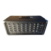
| Brand | Peavey |
|---|---|
| Model | PA 400 |
| Category | Music Mixer |
| Language | English |