60
| ENGLISH
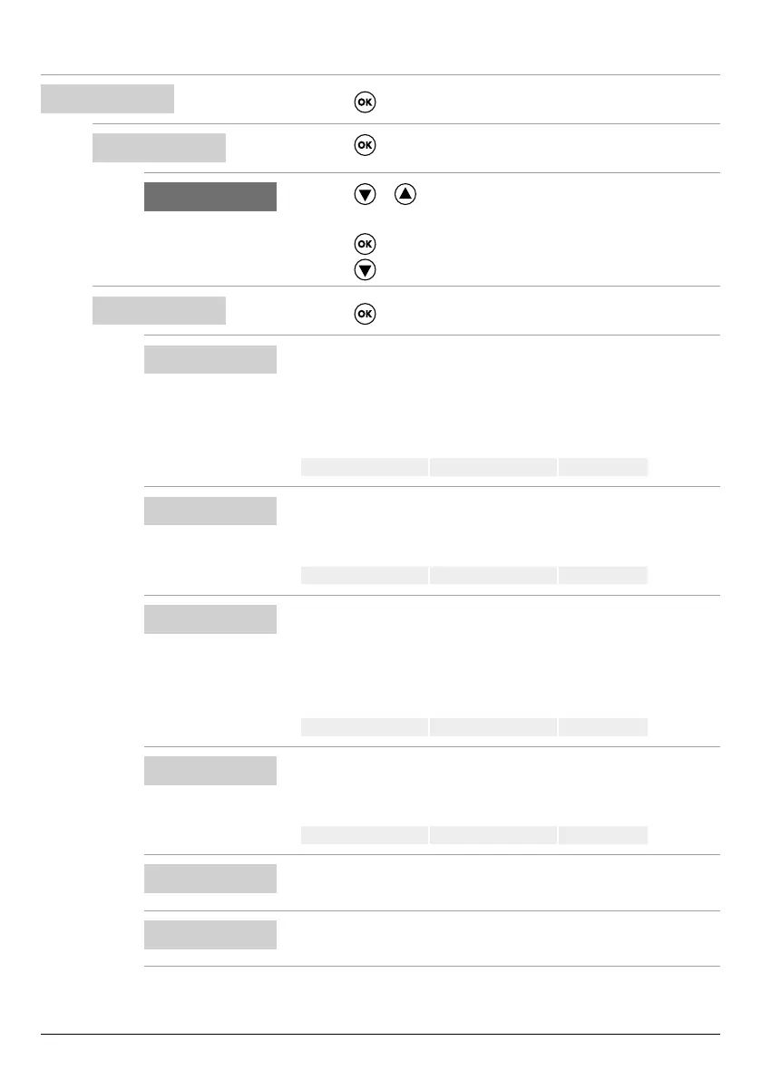
Conguring MODE 5
SELECT
MODE CONFIG
• Press the key to conrm the choice and enter the submenu.
9
MODE CONFIG
MODE:1
• Press the key to enter the submenu and change mode.
6 9
MODE:5
• Press the or key to select mode 5
(from modes 1 to 6)
• Press the
key to conrm the choice of MODE:5
• Press the
key to continue with the conguration
9
MODE CONFIG
SETUP
• Press the key to enter the mode 5 conguration submenu
9
MODE5 CONFIG
P1:3.0 bar
• Set the rst activation threshold to a specic pressure.
• This parameter denes the rst pressure threshold (P1), above which both
electric pumps are deactivated.
• If the pressure is below this set value (P1) minus the dierential value
(DP1), a single pump is activated according to the alternating logic.
Default 3 bar Range 0–40 bar Step 0.1
MODE5 CONFIG
DP1:0.5 bar
• Set the dierential value (DP1) to a specic pressure.
• This parameter denes the dierence between the activation and deactiva-
tion levels with respect to the rst activation threshold (P1)
Default 0.5 bar Range 0-P1 Step 0.1
MODE5 CONFIG
P2:2 bar
• Set the second activation threshold to a specic pressure.
• This parameter denes the second pressure threshold (P2), above which
one of the two electric pumps is deactivated.
• If the pressure is below this set value (P2) minus the dierential value
(DP2), the second pump is activated.
Default 2 bar Range 0–40 bar Step 0.1
MODE5 CONFIG
DP2:0.5 bar
• Set the dierential value (DP2) to a specic pressure.
• This parameter denes the dierence between the activation and deactiva-
tion levels with respect to the second activation threshold (P2)
Default 0.5 bar Range 0-P2 Step 0.1
MODE5 CONFIG
LOGIC:ALTERN.
• If the system has two electric pumps, enable (ALTERN.) or disable (SIN-
GLE) the alternating logic.
MODE5 CONFIG
DRY LOGIC:COS
• Set whether the dry running stop logic is based on the motor current read-
ing (CURR) or cosφ reading (COS)