EasyManua.ls Logo

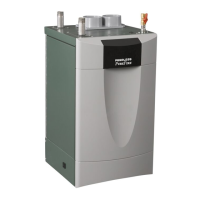
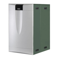
PEERLESS PureFire REV2 PF-110 User Manual

Default Icon
95 pages
To Next Page IconTo Next Page
Page #1 background imageLoading...
Page #1 background image
PUREFIRE
®
REV
2
Boilers
PF-50 PF-80 PF-110 PF-140 PF-210 PF-399
Gas
Installation,
Operation &
Maintenance
Manual
As an ENERGY STAR
®
Partner, PB Heat, LLC has determined that
this product meets the ENERGY STAR guidelines for energy efficiency.
®

Table of Contents

Question and Answer IconNeed help?

Do you have a question about the PEERLESS PureFire REV2 PF-110 and is the answer not in the manual?

PEERLESS PureFire REV2 PF-110 Specifications

General IconGeneral
BrandPEERLESS
ModelPureFire REV2 PF-110
CategoryBoiler
LanguageEnglish

Summary

USING THIS MANUAL

A. INSTALLATION SEQUENCE

Follows the order of installation steps for safety & efficiency.

B. SPECIAL ATTENTION BOXES

Explains DANGER, WARNING, CAUTION, NOTICE symbols for hazard awareness.

1. PREINSTALLATION

A. GENERAL

Covers boiler inspection, understanding connections, contractor qualifications, and low water cut-off.

B. CODES & REGULATIONS

Outlines installation standards, codes, and regulations.

Massachusetts Installation Requirements

Details requirements for CO detectors, signage, and exemptions for MA installations.

C. ACCESSIBILITY CLEARANCES

Specifies minimum clearances for boiler installation around the unit.

D. COMBUSTION AND VENTILATION AIR

Details requirements for air supply for combustion and ventilation.

5. Outdoor Combustion Air

Explains methods for providing outdoor air for combustion.

6. Combination Indoor and Outdoor Combustion Air

Details how to supplement indoor air with outdoor air for combustion.

7. Engineered Installations

Covers engineered combustion air installations requiring approval.

8. Mechanical Combustion Air Supply

Discusses mechanical systems for providing combustion air.

9. Louvers & Grills

Covers sizing and requirements for louvers and grilles.

10. Combustion Air Ducts

Details requirements for combustion air ducts.

E. PLANNING THE LAYOUT

1. Prepare sketches and notes

Emphasizes preparing layout sketches to minimize interferences.

2. Review related sections

Lists sections to review for layout considerations.

2. BOILER SET-UP

A. GENERAL

General guidelines for boiler installation location and support.

B. WALL MOUNTING

Instructions for mounting the boiler on a wall using brackets.

C. FLOOR STANDING INSTALLATION

Guidelines for installing the boiler in a floor-standing configuration.

3. VENTING & AIR INLET PIPING

A. GENERAL

General installation rules for venting and air intake systems.

B. APPROVED MATERIALS

Lists approved materials for vent and air inlet piping.

C. EXHAUST VENT/AIR INTAKE PIPE LOCATION

Details proper placement for vent and air intake pipes.

Sidewall Venting Configuration

Outlines clearances and configurations for sidewall venting.

D. EXHAUST VENT/AIR INTAKE PIPE SIZING

Provides guidelines for sizing exhaust and air intake pipes.

E. EXHAUST VENT/AIR INTAKE INSTALLATION

Details installation procedures for vent and air intake pipes.

F. EXHAUST TAPPING FOR VENT SAMPLE

Instructions for drilling and tapping vent pipe for gas sample.

G. BOILER REMOVAL FROM COMMON VENTING SYSTEM

Steps for safely removing a boiler from a common vent.

4. WATER PIPING & CONTROLS

A. GENERAL

General guidelines for water piping installation and system cleaning.

B. OPERATING PARAMETERS

Details minimum flow rates and system pressure for boiler operation.

C. SYSTEM COMPONENTS

Describes key components like pressure gauges, air separators, and expansion tanks.

D. SYSTEM PIPING

Provides diagrams and explanations for various system piping configurations.

E. FREEZE PROTECTION

Discusses measures and considerations for freeze protection in hydronic systems.

F. SPECIAL APPLICATIONS

Details piping for boilers used with chilled systems and forced air systems.

5. FUEL PIPING

A. GENERAL

General guidelines for fuel piping installation according to codes.

B. FUEL LINE SIZING

Instructions for determining correct fuel line size based on gas flow rate.

C. GAS SUPPLY PIPING - INSTALLATION

Covers installation of gas supply piping, including sediment traps.

D. GAS SUPPLY PIPING - OPERATION

Guidelines for operating the gas supply piping safely.

E. MAIN GAS VALVE - OPERATION

Details operation and adjustment of the main gas valve.

6. CONDENSATE DRAIN PIPING

A. GENERAL

General rules for condensate disposal and proper piping.

B. CONDENSATE SYSTEM

Explains the condensate system design to prevent backup and neutralize acid.

C. CONDENSATE DRAIN PIPE MATERIAL

Specifies materials resistant to acidic condensate for drain piping.

D. CONDENSATE DRAIN PIPE SIZING

Guidelines for sizing condensate drain piping.

7. ELECTRICAL CONNECTIONS

A. GENERAL

General wiring rules according to local codes and NEC.

B. CUSTOMER CONNECTIONS

Details low and line voltage customer connections for various boiler models.

C. ZONE CIRCULATOR WIRING

Shows wiring for a typical circulator zone relay.

D. INTERNAL WIRING

Lists internal wiring components and their functions.

8. BOILER CONTROL: INTERNAL WIRING & OPERATION

A. CONTROL OVERVIEW

Overview of the boiler control's function, modes, and features.

B. IGNITION SEQUENCE

Details the sequence of events during boiler ignition.

C. BOILER CONTROL

Explains pump modes and their configurations for various installations.

K. DEFAULTS

Describes how to restore factory or site default settings.

9. START-UP PROCEDURE

A. GENERAL

Initial steps to confirm power, gas, and proper installation before startup.

B. CHECK WATER PIPING

Steps to fill and purge the boiler and system with water.

C. CHECK GAS PIPING

Procedures for checking gas supply pressure and connections.

D. CHECK OPERATION

Verifies boiler shutdown at setpoint and checks combustion readings.

E. LIGHTING & OPERATING PROCEDURES

Step-by-step guide for lighting and operating the boiler safely.

10. TROUBLESHOOTING

A. BLOCKING ERRORS

Explains blocking errors, codes, and corrective actions.

B. LOCKING ERRORS

Details locking errors, codes, and the reset procedure.

C. ERROR MESSAGES IN A CASCADE SYSTEM

How errors are displayed in cascade systems.

D. WARNING ERRORS

Explains warning errors, sensor errors, and corrective actions.

11. MAINTENANCE

A. GENERAL (WITH BOILER IN USE)

Routine checks and observations for a boiler in operation.

B. WEEKLY (WITH BOILER IN USE)

Weekly maintenance task for flushing the low-water cut-off.

C. ANNUALLY (BEFORE START OF HEATING SEASON)

Annual inspection checklist for a qualified technician.

D. CONDENSATE CLEANING INSTRUCTIONS

Steps for cleaning condensate tanks and related components.

E. COMBUSTION CHAMBER COIL CLEANING INSTRUCTIONS

Procedure for cleaning heat exchanger coils and combustion chamber.

Inspect Exhaust Vent and Air Intake Vents

Inspects vents for support, integrity, obstructions, and corrosion.

12. BOILER DIMENSIONS & RATINGS

APPENDIX A. STATUS SCREENS

PureFire Condensing Boiler - Status Display

Shows various operational states like Standby, CH Demand, DHW Demand.

Central Heating Demand

Displays status during central heating operation, including ignition and modulation.

Domestic Hot Water Demand

Displays status during domestic hot water operation, including ignition and modulation.

Supply at Setpoint

Indicates when boiler supply temp meets setpoint or target, showing post-purge status.

Special Demand Functions

Shows status for Freeze Protection and Store Warm Hold functions.

Ignition/Flame Failure Handling

Displays status for ignition failures, flame failures, and retries.

Error Handling

Explains display for blocking errors and lockout errors.

Service Notification

Shows when service reminders are programmed and displayed.

Cascade (Multiple Boilers)

Displays status for master and dependent boilers in a cascade system.

Cascade (Multiple Boilers) continued

Shows call for heat and lockout alarm status for cascade systems.

APPENDIX B. USER MENU

User Menu

How to access and navigate the user menu for settings.

Status

Displays current supply, vent, outdoor temps, and circulator status.

Settings

Allows adjustment of CH setpoint, DHW settings, time, date, and units.

Messages

Displays last block and lockout messages for troubleshooting.

APPENDIX C. INSTALLER MENU

Installer Menu

Instructions on how to access and navigate the installer menu.

Status

Shows current supply setpoint, fan speeds, flame signal, and boiler run time.

Status continued

Displays blocking and locking errors, including timestamps.

Boiler Settings

Configures pump mode, installation location, and vent material.

CH (Central Heating) Settings

Configures CH mode, pump settings, and ramp delay.

CH (Central Heating) Settings continued

Configures outdoor reset, system type, warm weather shutdown, and boost function.

DHW (Domestic Hot Water) Settings

Configures DHW modes, priority, heat dump, and max allowable rate.

Service Notification

Sets up service reminders based on time, cycles, or date.

System Test

Allows forcing the control to operate at specific power levels for testing.

Cascade Settings

Configures boiler addresses, delay times, and temperature differentials for cascades.

Cascade Settings continued

Configures calculated setpoints, start/stop rates, and rotation interval for cascades.

Default Settings

Options to restore factory or site default settings.

APPENDIX D. COMBUSTION TEST RECORD

Peerless® PUREFIRE® Combustion Test Record

A form for recording combustion test data and jobsite information.

Related product manuals