28
A. GENERAL
1. All fuel piping to the PUREFIRE
®
boiler is to be in
accordance with local codes. In the absence of local
regulations refer to the National Fuel Gas Code, ANSI
Z223.1/NFPA 54.
2. Size and install fuel piping to provide a supply of gas
sufficient to meet the maximum demand of all
appliances supplied by the piping.
B. FUEL LINE SIZING
1. The required flow rate of gas fuel to the boiler can be
determined by the following.
The gas heating value can be supplied by the gas
supplier.
2. As an alternative, use Table 5.1 to determine the
required gas flow rate which uses typical heating
values for natural gas and liquefied petroleum (LP)
gas.
3. Table 5.2 shows the maximum flow capacity of
several pipe sizes based on 0.3" of pressure drop.
a. The values shown are based on a gas specific
gravity of 0.60 (Typical for natural gas).
b. Multiply the capacities listed by the correction
factors listed for gas with a specific gravity other
than 0.60 to obtain the corrected capacity.
4. Size and install the fuel gas supply piping for no more
than 0.5 inches of water pressure drop between the
gas regulator and the boiler.
C. GAS SUPPLY PIPING - INSTALLATION
1. Do not install any piping directly in front of the boiler
or along either side. Always provide access to the
front cover and side panel openings.
2. Install a sediment trap as shown in Figure 5.1. Be sure
to allow clearance from the floor or other horizontal
surface for removal of the pipe cap.
* Natural gas input rates are based on 1,000 Btu/ft
3
, LP input
rates are based on 2,500 Btu/ft
3
.
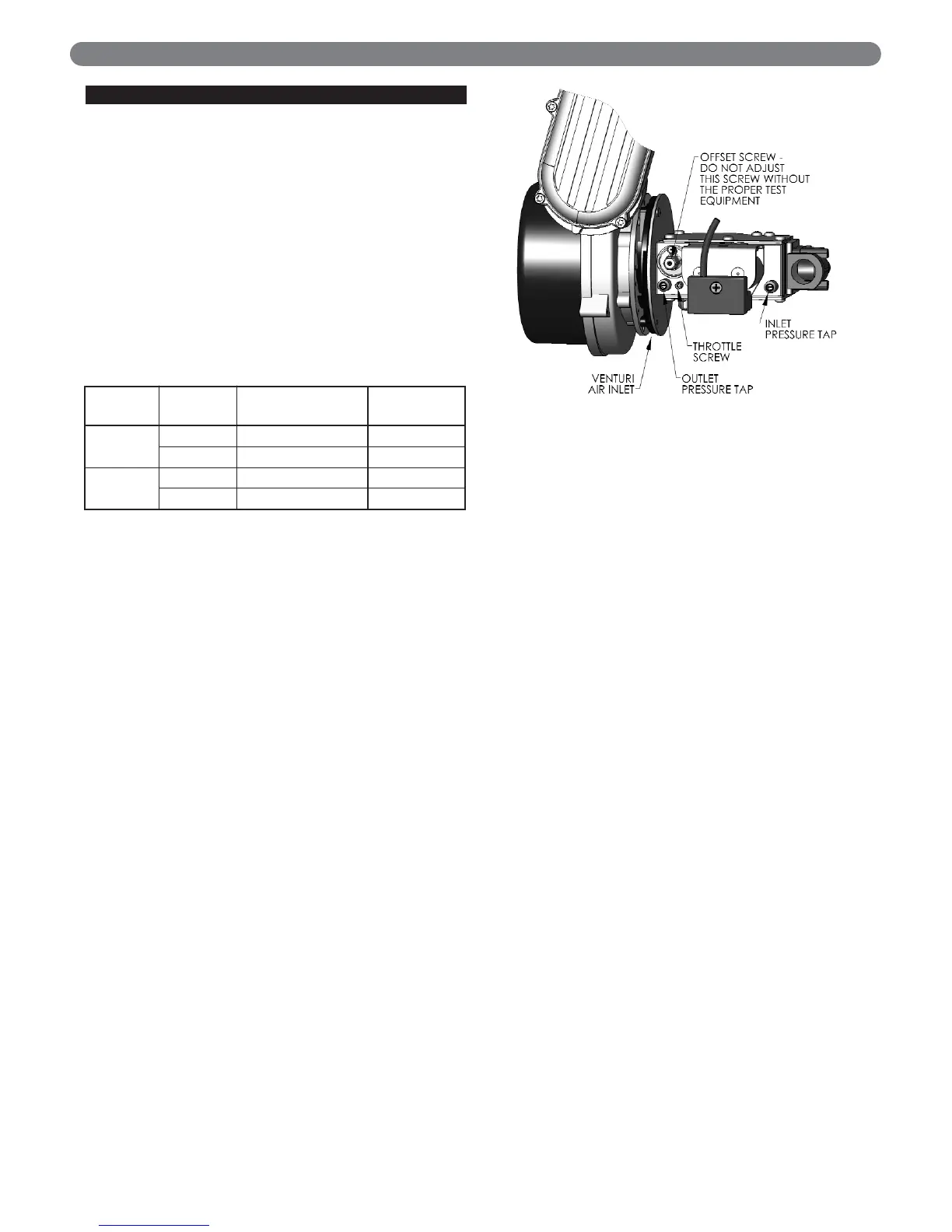
FUEL PIPING
5. FUEL PIPING
Use a pipe joint sealing compound that is resistant to
liquefied petroleum gas. A non-resistant compound
may lose sealing ability in the presence of this gas,
resulting in a gas leak. Gas leaks may potentially
cause an explosion or fire.
WARNING
PUREFIRE
®
Model
Required Input Rate*
Natural Gas ft
3
/hr
(m
3
/hr)
LP Gas ft
3
/hr
(m
3
/hr)
PF-50 50 (1.4) 20 (0.6)
PF-80 80 (2.3) 32 (0.9)
PF-110 110 (3.1) 44 (1.2)
PF-140 140 (4.0) 56 (1.6)
PF-210 210 (5.9) 84 (2.4)
PF-399 399 (11.3) 166 (4.7)
Table 5.1: Required Fuel Input
Pipe
Length
ft (m)
1/2" NPT
Pipe
3/4" NPT
Pipe
1" NPT
Pipe
1-1/4"
NPT
Pipe
1-1/2"
NPT
Pipe
10
(3.0)
132
(3.7)
278
(7.9)
520
(14.7)
1,050
(29.7)
1,600
(45.3)
20
(6.1)
92
(2.6)
190
(5.4)
350
(9.9)
730
(20.7)
1,100
(31.1)
30
(9.1)
73
(2.1)
152
(4.3)
285
(8.1)
590
(16.7)
890
(25.2)
40
(12.2)
63
(1.8)
130
(3.7)
245
(6.9)
500
(14.2)
760
(21.5)
50
(15.2)
56
(1.6)
115
(3.3)
215
(6.1)
440
(12.5)
670
(19.0)
60
(18.3)
50
(1.4)
105
(3.0)
195
(5.5)
400
(11.3)
610
(17.3)
70
(21.3)
46
(1.3)
96
(2.7)
180
(5.1)
370
(10.5)
560
(15.9)
80
(24.4)
43
(1.2)
90
(2.5)
170
(4.8)
350
(9.9)
530
(15.0)
90
(27.4)
40
(1.1)
84
(2.4)
160
(4.5)
320
(9.1)
490
(13.9)
100
(30.5)
38
(1.1)
79
(2.2)
150
(4.2)
305
(8.6)
460
(13.0)
The values are based on a specific gravity of 0.60 (typical for
natural gas). See Table 4.3 for capacity correction factors for
gases with other specific gravities.
Specific
Gravity
0.50 0.55 0.60 0.65 0.70 0.75
Correction
Factor
1.10 1.04 1.00 0.96 0.93 0.90
Specific
Gravity
0.80 0.85 0.90 1.00 1.10 1.20
Correction
Factor
0.87 0.84 0.82 0.78 0.74 0.71
Specific
Gravity
1.30 1.40 1.50 1.60 1.70 1.80
Correction
Factor
0.68 0.66 0.63 0.61 0.59 0.58
Table 5.2: Pipe Capacity:
Maximum Capacity of pipe in cubic feet per hour (cubic meters
per hour) with a pressure drop of 0.3" of water (75 Pa).
Boiler Input Rate
Gas Heating Value
Input Rate
(
ft
³
/
hr
)
=
(
Btu
/
hr
)
(
Btu
/
ft
³
)