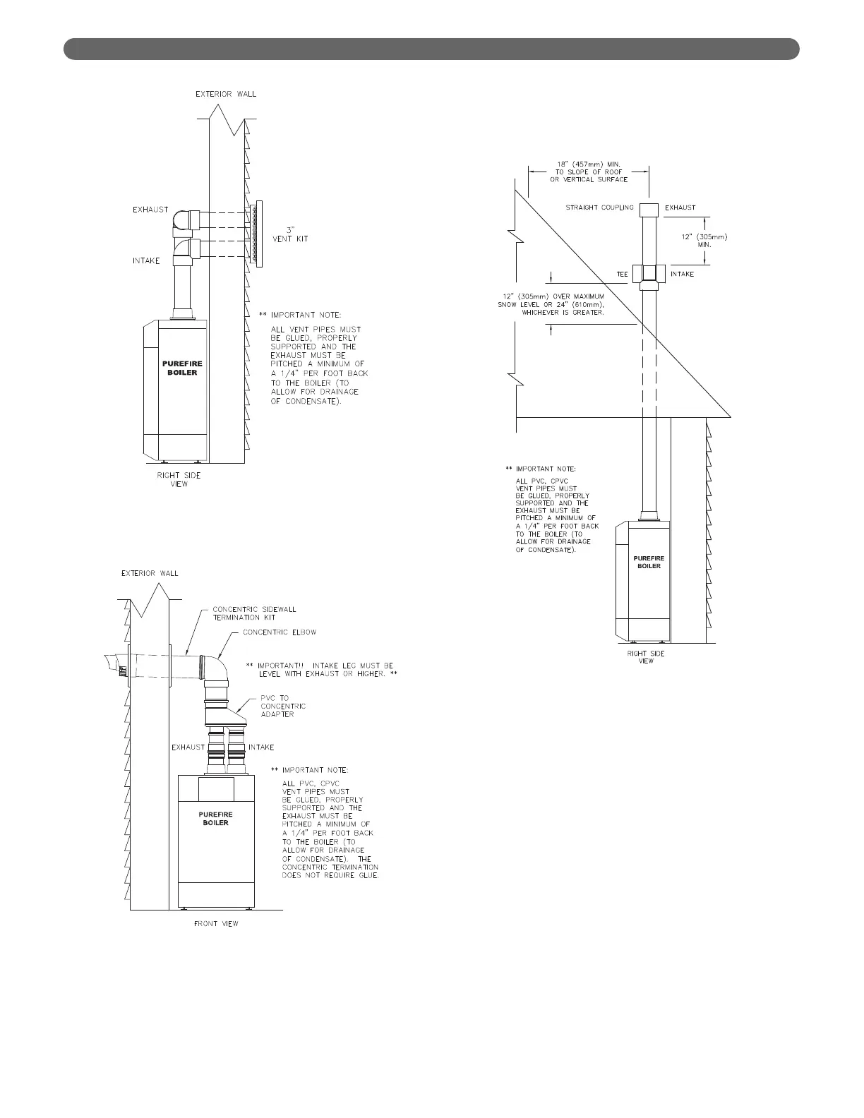
8. Vertical Venting Configuration:
a. Figure 3.9 shows the approved venting
configuration for vertical venting using the
standard fittings supplied.
b. Locate the air intake pipe inlet 12" above the
expected snow accumulation on the roof surface
or 24" above the roof surface, whichever is greater.
c. Locate the end of the exhaust vent pipe a minimum
of 12" above the inlet to the air intake pipe.
d. Figure 3.10 shows an approved vertical vent
configuration using the optional concentric vent
termination kit.
e. Figure 3.11 shows an option for routing the
exhaust and air inlet piping through an unused
chimney.
f. Figure 3.12 shows this option using inlet air from
a sidewall position.
g. Figure 3.13 shows an option for routing the
exhaust through an unused chimney with the
combustion air supplied from inside the building.
Be sure to note the requirements for combustion
air as listed under Section 1.D. "Combustion and
Ventilation Air". These requirements are in
accordance with the National Fuel Gas Code.
12
Figure 3.7: Optional Stainless Steel Vent Kit
Installation
Figure 3.8: Optional Concentric PVC Vent Kit
Installation
Figure 3.9: Standard Vertical Vent Installation
VENTING & AIR INLET PIPING