44
2. Installation Location & Vent Material:
The P
UREFIRE
®
boiler allows the installer to input the
installation location and the vent material used. This
information is used to determine the suitable vent
temperature limit based on National Codes. Table 8.6
shows the vent temperature limit based on the
location and vent material.
The P
UREFIRE
®
control will reduce the boiler firing rate
if the vent temperature approaches the vent
temperature limit. If the vent temperature continues to
rise, the control will shut down the boiler.
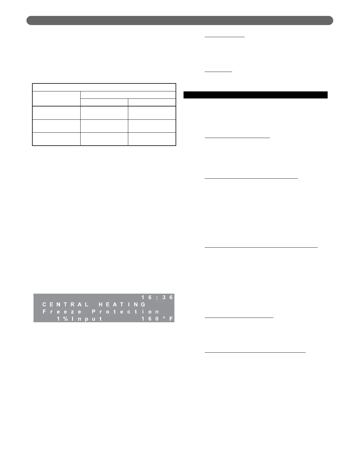
3. Freeze Protection:
The P
UREFIRE
®
boiler control is intended to prevent
the central heating system from freezing. The default
temperature to activate this function is 50°F (10°C).
If the supply temperature drops to below the freeze
protection setpoint, the general pump and/or the CH
pump (depending on pump mode) will be activated. If
the supply or return temperature drops more than 9°F
(5°C) below the setpoint, the control lights the boiler
using the ignition sequence described in section 8.B.
The control will operate the burner at minimum
power until the both the supply and return boiler
temperature are more than 9°F (5°C) above the freeze
protection setpoint.
While this function is active the interface panel will
display the following:
4. Blower Postpurge Time:
The P
UREFIRE
®
boiler control allows the installer to
change the burner postpurge timing. This is useful
under extreme conditions where high winds and
unusual wind currents prevent proper purging of the
combustion chamber.
This parameter is adjustable from 30 seconds to 120
seconds with the 30 second minimum as its default. It
is important to note that increased purge times may
slightly reduce the boiler efficiency.
5. Additional Safety Functions:
The P
UREFIRE
®
boiler control is equipped with terminals
for either a low water cutoff or a flow switch. The low
water cutoff option is the factory default and a factory
supplied jumper is installed. This jumper is to be
removed if a low water cutoff or flow switch is installed.
Low Water Cutoff
: The installer can connect the
power supply wires for a probe-type low water cutoff
to terminal #19 (Hot) and #20 (Neutral) in the main
terminal box. The contacts should be wired to
terminals #9 and #10.
Flow Switch
: If a flow switch is used, simply wire the
contacts to terminals #9 and #10 in the main
terminal box.
D. CENTRAL HEATING
1. Heating Modes:
Table 8.1 provides an overview of the central heating
(CH) modes. The following are detailed descriptions
of the operation of these modes:
Mode 0 – Indoor Thermostat
: This is the default mode
for the control. When this mode is selected, the
control starts the boiler in response to a demand from
the indoor thermostat. The boiler will target the User
selected setpoint each time there is a heat demand. In
this case, the outdoor thermostat is not required.
Mode 1 – Thermostat and Outdoor Reset
: In this
mode, the control uses the outdoor temperature to
calculate a target for the boiler setpoint.
The installer selects design temperatures and mild
weather temperatures on the installer menu. The
control then calculates a target supply temperature
based on the current outdoor temperature.
A detailed explanation of Outdoor Reset is provided
in section 8.D.3.
Mode 2 – Permanent Demand and Outdoor Reset
:
In this mode, the boiler control operates on a
permanent demand independent of room thermostats.
The boiler is held at a target supply temperature
calculated using the current outdoor temperature. In
this mode, a contact closure across terminals #1 and
#2 (CH T’Stat) will result in an 18°F temperature
setback. This can be used in conjunction with a timer
or switch for night or unoccupied setback periods. A
detailed explanation of Outdoor Reset is provided in
section 8.D.3.
Mode 3 – Permanent Demand
: Mode 3 is similar to
Mode 2 except that the boiler target is a constant user
defined setpoint. Again, a contact closure across
terminals #1 and #2 (CH T’Stat) will result in an
18°F temperature setback.
Mode 4 – 0-10 V Input to Modulate Setpoint
:
This feature requires the use of the PFA-1 Interface
Adapter kit (54271). With this adapter, this mode
allows the boiler setpoint to be controlled by an
external source using a 0-10 VDC analog signal. An
input of 2 volts is required to activate the call for heat.
With an input voltage of 2 volts, the setpoint
temperature will be 50°F and an input of 10 volts
corresponds to a setpoint of 195°F. The setpoint is
proportional between these values.
This mode is commonly used in conjunction with a
Building Management System (BMS) to control the
boiler setpoint based on the building requirements.
BOILER CONTROL: INTERNAL WIRING & OPERATION
Table 8.6: Vent Temperature Limits
Vent Limit Temperature
Vent
Material
Location
U.S.A. Canada
PVC
190°F
(80°C)
149°F
(65°C)
CPVC
230°F
(110°C)
190°F
(80°C)
PP(s)
230°F
(110°C)
230°F
(110°C)