17
FUEL PIPING
5. Refer to table 5.4 for minimum supply pressure for
the purpose of input adjustment.
6. Install the boiler such that the gas ignition system
components are protected from water (dripping,
spraying, rain, etc.) during appliance operation and
service (circulator replacement, condensate trap
clean out, control replacement, etc.)
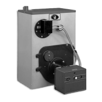
7. The boiler and its gas connection must be leak tested
before placing the boiler in operation.
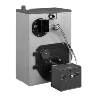
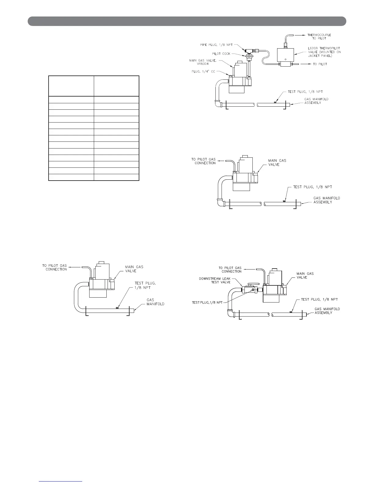
8. Typical gas train manifolds are illustrated in Figure
5.2 through 5.5.
Model
Supply
Pressure
(in. Water)
63-03L 5.00
63-03 5.00
63-04L 5.00
63-04 5.35
63-05L 5.00
63-05 5.00
63-06 5.56
64-07 5.00
64-08 5.27
64-09 5.00
64-10 5.00
64-11 5.00
64-12 5.10
Table 5.4: Minimum Supply
Pressure Natural Gas
Figure 5.2: Gas Train Manifold 63-03L
Through 63-06
Figure 5.5: Gas Train Manifold – Natural & LP Gas
64-09 Through 64-12
Figure 5.4: Gas Train Manifold – 64-07/08 LP Gas,
Standing Pilot & 64-07/08 Spark
Ignited Natural & LP Gas
Figure 5.3: Gas Train Manifold – 64-07 & 64-08
Natural Gas, Standing Pilot