21
ELECTRICAL
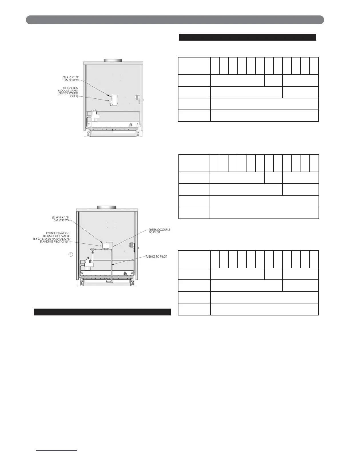
4. Mount the ignition module, if required (spark ignited
units only), as shown in Figure 7.4.
5. Mount the thermopilot valve (Johnson L62), if
required (standing pilot only on 64-07 & 64-08
Natural Gas), as shown in Figure 7.5.
C. INSTALL CONTROL WIRING
1. Wire the boiler according to the wiring diagram
supplied with the boiler (in the Control Envelope).
Figures 7.6 to 7.15 are provided for reference only.
2. Install all line voltage wiring in approved electrical
conduit.
3. Do not install single pole switches, including safety
controls, in the neutral leg.
D. WIRING DIAGRAM INDEX
Figure 7.4
Figure 7.5
63-03L
63-03
63-04L
63-04
63-05L
63-06
64-07
64-08
64-09
64-10
64-11
64-12
Standing Pilot,
Natural Gas
Fig. 7.6 Fig. 7.7 N/A
Standing Pilot,
LP Gas
Fig. 7.6 N/A
Spark Ignition,
Natural Gas
Fig 7.8
Spark Ignition,
LP Gas
Fig. 7.8
63-03L
63-03
63-04L
63-04
63-05L
63-06
64-07
64-08
64-09
64-10
64-11
64-12
Standing Pilot,
Natural Gas
Fig. 7.9
Fig.
7.10
N/A
Standing Pilot,
LP Gas
Fig. 7.9 N/A
Spark Ignition,
Natural Gas
Fig 7.11
Spark Ignition,
LP Gas
Fig. 7.11
63-03L
63-03
63-04L
63-04
63-05L
63-06
64-07
64-08
64-09
64-10
64-11
64-12
Standing Pilot,
Natural Gas
Fig. 7.12
Fig.
7.13
N/A
Standing Pilot,
LP Gas
Fig. 7.12 N/A
Spark Ignition,
Natural Gas
Fig 7.14
Spark Ignition,
LP Gas
Fig. 7.14
Table 7.1: Wiring Diagram Index - Water Boilers
Table 7.2: Wiring Diagram Index - Steam Boilers
w/Float LWCO
Table 7.3: Wiring Diagram Index - Steam Boilers
w/Probe LWCO