27
ELECTRICAL CONNECTIONS
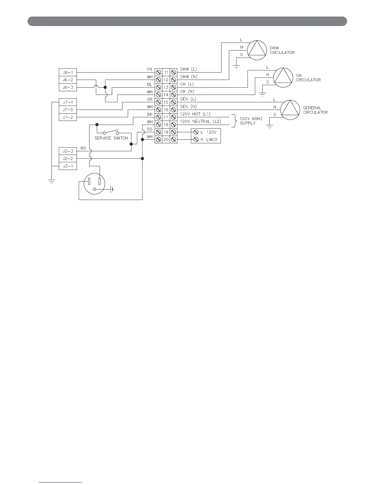
Figure 7.3: Line Voltage Customer Connections
7. Convenience Outlet: The convenience outlet is
provided for a condensate pump during operation. It
is not switched with the service switch to allow its use
for lighting during maintenance.
8. Flame Sensor: The flame sensor uses the principal of
flame rectification to sense the burner flame. This is
located on the right side of the heat exchanger front
plate. After ignition, the control also senses flame
through the ignition electrode.
9. Gas Valve: The gas valve is connected through a
special cord and connector. The connector is attached
to the valve with a screw.
10. Ignition Electrode: This electrode is located on the left
side of the heat exchanger front plate. A 10,000 volt
charge is initiated by the control to provide a spark for
lighting the burner. After the burner lights, and no
spark is present, the control uses this electrode as a
second source of flame detection.
11. Combustion Air Fan: The combustion air fan has two
connections. There is a 120 volt power connection (3-
wire) and a low voltage control connection (4-wire).